Mechanical Engineering Exam > Mechanical Engineering Notes > Mechanical Engineering SSC JE (Technical) > Vapour Absorption System
Vapour Absorption System | Mechanical Engineering SSC JE (Technical) PDF Download

VAPOUR ABSORPTION SYSTEM
In this system, absorber, pump and generator combindely replaces compressor of vapour compression system. The refrigerant flows as
absorber ® Pump® Generator® Condenser® Expander® Evaporator
- Absorber: Here lies a weak solution which after absorbing the refrigerant becomes rich solution.
- Pump:it pumps rich solution raising its pressure to condenser pressure.
- Generator: It distills vapour refrigerant from rich solution making it weak solution for recycling in absorber.
the cycle of rich solution flows as absorber ® pump ® generator ® valve ® absorber
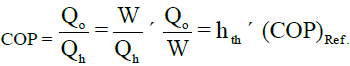
COP = 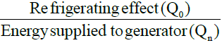
- Vapour absorption system may be considered as a combination of heat engine & refrigerating machine.
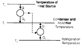
Maximum COP
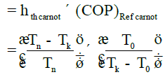
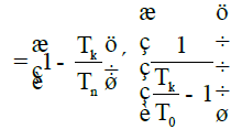
- So for maximum COP
- Th should be as high as possible
- Tk should be as low as possible
- T0 should be as high as possible
- COP of vapour absorption system first increases with generator temperature
(Th). reaches an optimum then it decreases
REQUIREMENT OF REFRIGERANT ABSORBENT PAIR
- Low viscosity to minimize pump work
- Low freezing point
- Chemical & thermal stability
- Refrigerant should be highly soluble in absorbent
- Their boiling point difference should be large.
Ex. Refrigerant NH3 + Absorbent H2O
Refrigerant H2O + Absorbent LiBr2
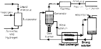
ELECTROLUX REFRIGERATOR
- It works on 3 fluid System e.g.,
NH3 + H2O + H2
- There is no solution circulation pump
- Third fluid remains in the evaporator.
- H2 is chosen as it is non corrosive & insoluble in water.
- Two U bends are provided to prevent H2 from going to solution
- The cycle runs on the basis of partial pressure variation.
The document Vapour Absorption System | Mechanical Engineering SSC JE (Technical) is a part of the Mechanical Engineering Course Mechanical Engineering SSC JE (Technical).
All you need of Mechanical Engineering at this link: Mechanical Engineering
|
5 videos|103 docs|59 tests
|
FAQs on Vapour Absorption System - Mechanical Engineering SSC JE (Technical)
| 1. What is a vapour absorption system in mechanical engineering? |  |
Ans. A vapour absorption system is a type of refrigeration system that uses a heat source to generate refrigeration effect. It works on the principle of absorption, where a refrigerant vapor is absorbed into a solution and then desorbed to produce cooling. This system is commonly used in industrial applications where waste heat or low-grade heat is available.
| 2. How does a vapour absorption system differ from a vapour compression system? | |
Ans. The main difference between a vapour absorption system and a vapour compression system is the method used to compress the refrigerant. In a vapour absorption system, the refrigerant is absorbed into a solution and then desorbed using a heat source, whereas in a vapour compression system, a mechanical compressor is used to directly compress the refrigerant. Vapour absorption systems are generally more energy-efficient and environmentally friendly, but they are also more complex and require a heat source.
| 3. What are the advantages of using a vapour absorption system? | |
Ans. Some advantages of using a vapour absorption system include:
1. Energy efficiency: Vapour absorption systems can utilize waste heat or low-grade heat sources, making them more energy-efficient compared to vapour compression systems.
2. Environmentally friendly: Vapour absorption systems do not require ozone-depleting refrigerants, making them more environmentally friendly.
3. Flexibility in heat source: Vapour absorption systems can use a variety of heat sources, such as natural gas, steam, or solar energy, providing flexibility in system design and operation.
4. Low noise levels: Vapour absorption systems generally produce less noise compared to vapour compression systems, making them suitable for noise-sensitive environments.
5. Long lifespan: Vapour absorption systems are known for their durability and long lifespan, resulting in lower maintenance and replacement costs over time.
| 4. What are the applications of vapour absorption systems in mechanical engineering? | |
Ans. Vapour absorption systems find various applications in mechanical engineering, including:
1. Industrial refrigeration: Vapour absorption systems are commonly used in large-scale industrial refrigeration applications, such as food processing, chemical manufacturing, and cold storage facilities.
2. Air conditioning: Vapour absorption systems can be used for air conditioning in commercial buildings, hotels, and hospitals, especially in areas where waste heat or low-grade heat is readily available.
3. Power generation: Vapour absorption systems can be integrated with power plants to utilize waste heat for cooling purposes, improving overall energy efficiency.
4. District cooling: Vapour absorption systems can be used in district cooling systems, where a centralized cooling plant supplies chilled water to multiple buildings, reducing the energy consumption of individual cooling systems.
5. Solar cooling: Vapour absorption systems can be combined with solar thermal collectors to provide cooling using renewable energy sources, making them suitable for off-grid or environmentally conscious applications.
| 5. What are the challenges or limitations of vapour absorption systems in mechanical engineering? | |
Ans. Some challenges or limitations associated with vapour absorption systems include:
1. High initial cost: Vapour absorption systems often have higher initial costs compared to vapour compression systems due to their complex design and additional components required.
2. Size and weight: Vapour absorption systems are typically larger and heavier than vapour compression systems, making them more challenging to install and transport.
3. Limited cooling capacity: Vapour absorption systems usually have lower cooling capacities compared to vapour compression systems, which may limit their applications in certain industries or environments.
4. Complex maintenance: Vapour absorption systems require regular maintenance and servicing, including monitoring the concentration of the absorbent solution and maintaining proper heat source temperatures.
5. Limited availability of suitable heat sources: Vapour absorption systems heavily rely on the availability of waste heat or low-grade heat sources, which may not always be readily available or economical to utilize.
About this Document

1.1K Views

4.74/5
Rating

Oct 22, 2025
Last updated
Related Exams
Document Description: Vapour Absorption System for Mechanical Engineering 2025 is part of Mechanical Engineering SSC JE (Technical) preparation.
The notes and questions for Vapour Absorption System have been prepared according to the Mechanical Engineering exam syllabus. Information about Vapour Absorption System covers topics
like and Vapour Absorption System Example, for Mechanical Engineering 2025 Exam. Find important definitions, questions, notes, meanings, examples, exercises and tests below for Vapour Absorption System.
Introduction of Vapour Absorption System in English is available as part of our Mechanical Engineering SSC JE (Technical)
for Mechanical Engineering & Vapour Absorption System in Hindi for Mechanical Engineering SSC JE (Technical) course.
Download more important topics related with notes, lectures and mock test series for Mechanical Engineering
Exam by signing up for free. Mechanical Engineering: Vapour Absorption System | Mechanical Engineering SSC JE (Technical)
Description
Full syllabus notes, lecture & questions for Vapour Absorption System | Mechanical Engineering SSC JE (Technical) - Mechanical Engineering | Plus excerises question with solution to help you revise complete syllabus for Mechanical Engineering SSC JE (Technical) | Best notes, free PDF download
Information about Vapour Absorption System
In this doc you can find the meaning of Vapour Absorption System defined & explained in the simplest way possible. Besides explaining types of
Vapour Absorption System theory, EduRev gives you an ample number of questions to practice Vapour Absorption System tests, examples and also practice Mechanical Engineering
tests

Related Searches
Vapour Absorption System | Mechanical Engineering SSC JE (Technical)
,Objective type Questions
,Extra Questions
,Vapour Absorption System | Mechanical Engineering SSC JE (Technical)
,mock tests for examination
,past year papers
,Important questions
,Sample Paper
,study material
,practice quizzes
,Viva Questions
,MCQs
,Free
,ppt
,Previous Year Questions with Solutions
,shortcuts and tricks
,video lectures
,Exam
,Summary
,Semester Notes
,Vapour Absorption System | Mechanical Engineering SSC JE (Technical)
;


Additional Information about Vapour Absorption System for Mechanical Engineering Preparation
Vapour Absorption System Free PDF Download
The Vapour Absorption System is an invaluable resource that delves deep into the core of the Mechanical Engineering exam.
These study notes are curated by experts and cover all the essential topics and concepts, making your preparation more efficient and effective.
With the help of these notes, you can grasp complex subjects quickly, revise important points easily,
and reinforce your understanding of key concepts. The study notes are presented in a concise and easy-to-understand manner,
allowing you to optimize your learning process. Whether you're looking for best-recommended books, sample papers, study material,
or toppers' notes, this PDF has got you covered. Download the Vapour Absorption System now and kickstart your journey towards success in the Mechanical Engineering exam.
Importance of Vapour Absorption System
The importance of Vapour Absorption System cannot be overstated, especially for Mechanical Engineering aspirants.
This document holds the key to success in the Mechanical Engineering exam.
It offers a detailed understanding of the concept, providing invaluable insights into the topic.
By knowing the concepts well in advance, students can plan their preparation effectively.
Utilize this indispensable guide for a well-rounded preparation and achieve your desired results.
Vapour Absorption System Notes
Vapour Absorption System Notes offer in-depth insights into the specific topic to help you master it with ease.
This comprehensive document covers all aspects related to Vapour Absorption System.
It includes detailed information about the exam syllabus, recommended books, and study materials for a well-rounded preparation.
Practice papers and question papers enable you to assess your progress effectively.
Additionally, the paper analysis provides valuable tips for tackling the exam strategically.
Access to Toppers' notes gives you an edge in understanding complex concepts.
Whether you're a beginner or aiming for advanced proficiency, Vapour Absorption System Notes on EduRev are your ultimate resource for success.
Vapour Absorption System Mechanical Engineering Questions
The "Vapour Absorption System Mechanical Engineering Questions" guide is a valuable resource for all aspiring students preparing for the
Mechanical Engineering exam. It focuses on providing a wide range of practice questions to help students gauge
their understanding of the exam topics. These questions cover the entire syllabus, ensuring comprehensive preparation.
The guide includes previous years' question papers for students to familiarize themselves with the exam's format and difficulty level.
Additionally, it offers subject-specific question banks, allowing students to focus on weak areas and improve their performance.
Study Vapour Absorption System on the App
Students of Mechanical Engineering can study Vapour Absorption System alongwith tests & analysis from the EduRev app,
which will help them while preparing for their exam. Apart from the Vapour Absorption System,
students can also utilize the EduRev App for other study materials such as previous year question papers, syllabus, important questions, etc.
The EduRev App will make your learning easier as you can access it from anywhere you want.
The content of Vapour Absorption System is prepared as per the latest Mechanical Engineering syllabus.
|
© EduRev
|
Education Revolution
|


|


Signup to see your scores
go up within 7 days!
Access 1000+ FREE Docs, Videos and Tests
Takes less than 10 seconds to signup