Measurements And Experimentation Chapter Notes | Physics Class 9 ICSE PDF Download
| Table of contents |
|
| Systems of Unit and Units in S.I. System |
|
| Measurements Using Common Instruments |
|
| Least Count of a Measuring Instrument |
|
| Vernier Callipers |
|
| Measurement of Time and Simple Pendulum |
|

Systems of Unit and Units in S.I. System
Need of Unit for Measurement
Physics and other sciences rely on experimental studies that involve measurements. To measure a physical quantity, we compare it to a standard quantity of the same type, determining how many times the standard is contained within the measured quantity. This process of comparison is called measurement, where the standard quantity is known as the unit. Different types of quantities require different units.
A unit is a fixed quantity used as a reference to measure other quantities of the same kind. The result of a measurement is expressed by two components:
- The unit used for measurement.
- The numerical value, indicating how many times the unit is contained in the quantity.
For example:
- A cloth measuring 10 meters means the unit (meter) is contained 10 times in its length.
- A 5-kilogram bag of sugar indicates the unit (kilogram) is contained 5 times in its mass.
The magnitude of a physical quantity is expressed as:
Physical Quantity = Numerical Value × Unit
Criteria for Choosing a Unit
A suitable unit must:
- Be of a convenient size.
- Be clearly defined without ambiguity.
- Be reproducible.
- Remain constant across time and space.
The last three criteria ensure the unit is universally accepted.
Types of Units
Units are classified into two categories:
- Fundamental (Basic) Units: These are independent and cannot be derived from other units. Examples include units for mass (kilogram), length (meter), time (second), temperature (kelvin), electric current (ampere), and amount of substance (mole).
- Derived Units: These are expressed in terms of fundamental units. For instance:
- Area is measured as length × length (e.g., square meters, m²).
- Volume is length × length × length (e.g., cubic meters, m³).
- Speed is derived by dividing length by time (e.g., meters per second, m/s).
Systems of Unit
- Fundamental quantities in mechanics are length, mass, and time.
- Three historical systems of units:
- C.G.S. system: Length (centimeter, cm), Mass (gram, g), Time (second, s).
- F.P.S. system: Length (foot, ft), Mass (pound, lb), Time (second, s).
- M.K.S. system: Length (meter, m), Mass (kilogram, kg), Time (second, s).
- These systems are outdated; the S.I. system (Systeme Internationale d’Unites) is now used.
- S.I. system includes seven fundamental units and two complementary units:
- Length: meter (m).
- Mass: kilogram (kg).
- Time: second (s).
- Temperature: kelvin (K).
- Luminous intensity: candela (cd).
- Electric current: ampere (A).
- Amount of substance: mole (mol).
- Angle: radian (rd).
- Solid angle: steradian (st-rd).
- Prefixes are used for large or small measurements:
- Big measurements: deca (da, 101), hecto (h, 102), kilo (k, 103), mega (M, 106), giga (G, 109), tera (T, 1012), peta (P, 1015), exa (E, 1018), zetta (Z, 1021), yotta (Y, 1024).
- Small measurements: deci (d, 10-1), centi (c, 10-2), milli (m, 10-3), micro (μ, 10-6), nano (n, 10-9), pico (p, 10-12), femto (f, 10-15), atto (a, 10-18), zepto (z, 10-21), yocto (y, 10-24).
- Example: 2.5 GHz = 2.5 × 10⁹ Hz, 5.0 pF = 5.0 × 10⁻¹² F.
Units of Length
S.I. unit of length is meter (m).
Historical definitions of meter:
- 1889: Distance between two marks on a platinum-iridium rod at 0°C.
- 1960: 1,650,763.73 times the wavelength of a Krypton-86 orange-red spectral line or 1,553,164.1 times the red line in cadmium’s emission spectrum.
- 1983: Distance light travels in 1/299,792,458 of a second in air or vacuum.
Subunits of meter:
- Centimeter (cm): 1 cm = 10-2 m.
- Millimeter (mm): 1 mm = 10-3 m = 10-1 cm.
- Micrometer (μm): 1 μm = 10-6 m = 10-4 cm = 10-3 mm.
- Nanometer (nm): 1 nm = 10-9 m.
Multiple unit: Kilometer (km): 1 km = 103 m.
Non-metric units for large distances:
- Astronomical unit (A.U.): Mean distance between Earth and Sun, 1 A.U. = 1.496 × 10¹¹ m.
- Light year (ly): Distance light travels in one year, 1 ly = 9.46 × 10¹⁵ m = 9.46 × 10¹² km.
- Parsec: Distance where 1 A.U. subtends an angle of one second, 1 parsec = 3.08 × 10¹⁶ m = 3.26 ly.
Non-metric units for small distances:
- Angstrom (Å): 1 Å = 10-10 m = 10-8 cm = 10-1 nm.
- Fermi (f): 1 f = 10-15 m.
Relationships: 1 μm = 10,000 Å, 1 nm = 10 Å.
Since 1 μm = 10-6 m, size = 4.6 × 10⁻⁶ m.
Units of Mass
- S.I. unit of mass is kilogram (kg).
Definitions:
- 1889: Mass of a platinum-iridium cylinder at the International Bureau of Weights and Measures.
- Also, mass of 1 liter of water at 4°C.
Subunits:
- Gram (g): 1 g = 10-3 kg.
- Milligram (mg): 1 mg = 10-6 kg = 10-3 g.
Multiple units:
- Quintal: 1 quintal = 100 kg.
- Metric tonne: 1 metric tonne = 1000 kg = 10 quintal.
Non-metric unit:
- Atomic mass unit (a.m.u. or u): 1 u = 1/12th the mass of a carbon-12 atom = 1.66 × 10⁻²⁷ kg.
- Solar mass: Mass of the Sun, 1 solar mass = 2 × 1030 kg.
Since 1 u = 1.66 × 10⁻²⁷ kg, mass = 16.0 × 1.66 × 10-27 = 2.656 × 10⁻²⁶ kg.
Units of Time
S.I. unit of time is second (s).
Definitions:
- Second: 1/86400th of a mean solar day (time for Earth to complete one rotation).
- 1956: 1 s = 1/31,556,925.9747th of the year 1900 (365.2422 days).
- 1964: Time for 9,192,631,770 vibrations of cesium-133 atom’s radiation.
Smaller units:
- Millisecond (ms): 1 ms = 10-3 s.
- Microsecond (μs): 1 μs = 10-6 s.
- Shake: 1 Shake = 10-8 s.
- Nanosecond (ns): 1 ns = 10-9 s.
Bigger units:
- Minute (min): 1 min = 60 s.
- Hour (h): 1 h = 3600 s.
- Day: 1 day = 86400 s.
- Month: Approximately 30 days = 2.592 × 10⁶ s.
- Lunar month: 29.5 days = 2.5488 × 10⁶ s.
- Year (yr): 1 yr = 365 days = 3.1536 × 10⁷ s.
- Leap year: 366 days.
- Decade: 10 years = 3.1536 × 10⁸ s.
- Century: 100 years = 3.16 × 10⁹ s (24 leap years, 76 normal years).
- Millennium: 1000 years = 3.16 × 10¹⁰ s.
Leap year rules:
- Years divisible by 4 are leap years (e.g., 2000, 2004).
- Century years are not leap years unless divisible by 400 (e.g., 2000 was a leap year, 2100 is not).
Some Examples of Derived Units
Derived units are expressed in terms of fundamental units.
Examples:
- Area: m2 (length × breadth).
- Volume: m3 (length × breadth × height).
- Density: kg m-3 (mass/volume).
- Speed/Velocity: m s-1 (distance/time).
- Acceleration: m s-2 (velocity/time).
- Force: kg m s-2 or newton (N) (mass × acceleration).
- Work/Energy: kg m2 s-2 or joule (J) (force × displacement).
- Momentum: kg m s-1 or N s (mass × velocity).
- Moment of force/Torque: kg m2 s-2 or N m (force × distance).
- Power: kg m2 s-3 or watt (W) (work/time).
- Pressure: kg m-1 s-2 or pascal (Pa) (force/area).
- Frequency: s-1 or hertz (Hz) (1/time period).
- Electric charge: A s or coulomb (C) (current × time).
- Electric potential/EMF: kg m2 A-1 s-3 or volt (V) (work/charge).
- Electrical resistance: kg m2 A-2 s-3 or ohm (Ω) (potential/current).
- Electrical power: V A or watt (W) (potential × current).
Special names (e.g., newton, joule) are given to some derived units for convenience.
Guidelines for Writing the Units
- Symbols for units not named after scientists use small letters (e.g., m for meter, s for second).
- Symbols for units named after scientists use a capital first letter (e.g., N for newton, J for joule).
- Full unit names always start with a lowercase letter (e.g., newton, not Newton).
- Compound units use a dot, cross, or space (e.g., N.m, N × m, N m).
- Units formed by division use negative powers (e.g., velocity: m s-1).
- Unit symbols are not pluralized (e.g., 10 m, not 10 ms).
- Use one prefix per unit (e.g., GW, not kMW).
- Prefix and unit symbol together form a new symbol (e.g., km3 = (103 m)3 = 109 m3).
Measurements Using Common Instruments
Least Count of a Measuring Instrument
To measure physical quantities like length, mass, time, or current, specific instruments are used, such as a meter rule or vernier caliper for length, a balance for mass, a stopwatch for time, a thermometer for temperature, or an ammeter for current. Each instrument has a limit to its measurement accuracy, known as its least count.
The least count of an instrument is the smallest measurement it can accurately detect, corresponding to the value of the smallest division on its scale. For example:
- A meter rule with divisions every 1 mm has a least count of 1 mm (0.1 cm).
- A stopwatch with 10 divisions between 0 and 5 seconds has a least count of 0.5 s (5 s ÷ 10).
- An ammeter with 5 divisions between 0 and 1 A has a least count of 0.2 A (1 A ÷ 5).
A smaller least count indicates a more precise instrument.
Measurement of Length
A meter rule, typically marked from 0 to 100 cm with 1 mm (0.1 cm) subdivisions, is commonly used to measure length. It can measure length accurately only to one decimal place of a centimeter (e.g., 1 mm). It cannot measure to a higher precision, such as the second decimal place, because it can only read to the nearest division mark. For greater accuracy, instruments like vernier calipers or screw gauges, which have smaller least counts, are used.
Principle of Vernier
The vernier method, developed by Pierre Vernier, allows length measurements accurate to the second decimal place of a centimeter (0.01 cm or 0.1 mm). It uses two scales:
- Main scale: Fixed, with divisions typically at 1 mm intervals.
- Vernier scale: Slides along the main scale, with divisions designed so that n vernier divisions equal (n-1) main scale divisions. Commonly, 10 vernier divisions equal 9 main scale divisions (9 mm), making each vernier division 0.9 mm (9 mm ÷ 10).
The least count (LC) or vernier constant is the difference between one main scale division and one vernier scale division. It is calculated as:
Least count (L.C.): Smallest length measurable, calculated as L.C. = x/n, where x = value of one main scale division, n = number of vernier scale divisions.
Vernier constant: Same as least count.
Zero error:
- Occurs when jaws are closed, but vernier scale’s zero does not align with main scale’s zero.
- Positive zero error: Vernier zero is to the right of main scale zero.
- Negative zero error: Vernier zero is to the left of main scale zero.
- Correction: True length = observed length - zero error (with sign).
Measurement procedure:
- Check least count and zero error.
- Place object between jaws, close gently.
- Note main scale reading (a).
- Find vernier division (p) aligning with main scale.
- Calculate vernier scale reading = p × L.C.
- Observed length = a + (p × L.C.).
- Subtract zero error to get true length.
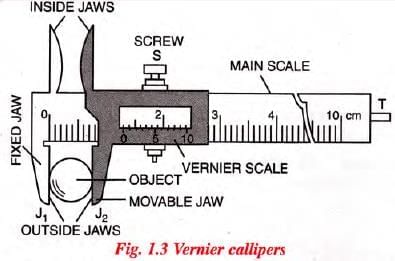
Vernier Callipers
A vernier callipers is also called the slide callipers. It is used to measure the length of a rod, the diameter of a sphere, the internal and external diameters of a hollow cylinder, the depth of a small beaker (or bottle), etc.
(a) Description
- As shown in Fig. 1.3, a vernier calliper consists of a long, thin steel strip with a jaw labeled J1 at one end.
- This strip has a main scale marked in divisions of 1 mm each.
- A smaller steel strip with a jaw labeled J2 can slide along the main scale.
- This sliding strip has a vernier scale, where 10 divisions span the length of 9 mm on the main scale.
- For greater precision, the vernier scale may have 20, 25, or 50 divisions, corresponding to 19, 24, or 49 mm on the main scale (always one division less than the total number of vernier divisions).
- The sliding vernier scale moves over the main scale and can be fixed in place using a screw (S).
- The jaws are parallel and extend on either side of the main scale to hold the object being measured.
- The lower jaws, called outside jaws, measure external dimensions like the length of a rod, the diameter of a sphere, or the outer diameter of a cylinder.
- The upper jaws, known as inside jaws, measure internal dimensions, such as the inner diameter of a hollow cylinder or pipe.
- A thin, long strip (T) is attached to the vernier scale at the back of the main scale.
- When jaws J1 and J2 are closed, the end of strip T touches the end of the main scale strip.
- This strip T is used to measure the depth of a small container, such as a beaker or bottle.
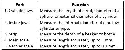
The table below gives the main parts of a vernier callipers with their functions.
Vernier callipers—main parts and their functions.
(b) Least Count of Vernier Callipers
The least count of a vernier calliper is the difference between one division on the main scale and one division on the vernier scale. This value can be reduced by either increasing the number of divisions on the vernier scale or decreasing the value of each division on the main scale.
(c) Zero Error in Vernier Callipers
When the movable jaw J2 is brought into contact with the fixed jaw J1, the zero mark on the vernier scale should align with the zero mark on the main scale. If it does, the calliper is free of zero error, and the end of strip T will also touch the end of the main scale strip. However, if there’s a mechanical error and the zero marks do not align when the jaws are closed, the calliper has a zero error. This error is the distance between the zero mark on the main scale and the zero mark on the vernier scale. Accounting for this error is essential for accurate measurements.
Types of Zero Error: The zero error is of the following two kinds :
(i) Positive zero error, and
(ii) Negative zero error
(i) Positive zero error:
- On bringing the two jaws together, if the zero mark of the vernier scale is on the right of the zero mark of the main scale, the zero error is said to be positive.
- Fig. 1.4 shows the two scales of a vernier callipers with positive zero error.
- The positive zero error is equal to the length between the zero mark of the vernier scale from the zero mark of the main scale.
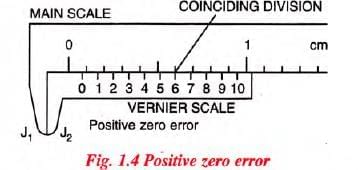
To find this error, we note that division of the vernier scale which coincides with any division of the main scale. The number of this vernier division when multiplied by the least count of the vernier, gives the zero error.
For example, for the scales shown in Fig. 1.4, the least count is 0 0 1 cm and the 6th division of vernier scale coincides with a main scale division.
∴ Zero error = + 6 × L.C. = + 6 × 0.01 cm
= + 0.06 cm.
(ii) Negative zero error:
- On bringing the two jaws together, if the zero mark of the vernier scale is to the left of the zero mark of the main scale, the zero error is said to be negative.
- Fig. 1.5 shows the two scales of a vernier callipers with negative zero error.
- The negative zero error is equal to the length between the zero mark of the main scale from the zero mark of the vernier scale.
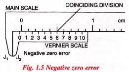
- To find this error, we note that the division of the vernier scale which coincides with any division of the main scale.
- The number of this vernier division is subtracted from the total number of divisions on the vernier scale and then the difference is multiplied by the least count.
- In Fig. 1.5, the least count is 0.01 cm and the sixth division of the vernier scale coincides with a certain division of the main scale.
- The total number of divisions on the vernier are 10.
∴ Zero error = - (10 - 6) x L.C. = - 4 x 0-01 cm = - 0.04 cm.
(d) Correction due to zero error i.e., correct measurement with a vernier callipers having a zero error
To get the correct reading, the zero error with its proper sign is always subtracted from the observed reading, i.e.,Thus the positive zero error gets subtracted from the observed reading, while the negative zero error gets added to the observed reading.
(e) Measurement of length of an object with a vernier callipers Procedure :
(i) Find the least count and zero error of the vernier callipers.
(ii) Move the ja w J2 away from the J1 and Place the object to be measured, between the jaws J1 and J2. Move the jaw J2 towards the jaw J1 till it touches the object. Tighten the screw S to fix the vernier scale in its position.
(iii) Note the main scale reading.
(iv) Note that division p of vernier scale coincides or is in line with any division of the main scale. Multiply this vernier division p with the least count. This is the vernier scale reading i.e., Vernier scale reading = p × L.C.
Principle of a Screw
- An ordinary screw has threads on it at an equal distance along its length.
- On rotating the head of the screw, it moves forward or backward linearly along its axis.
- The linear distance which the screw moves in one round is equal to the distance between the two consecutive threads on it.
- This distance is called the pitch of the screw.
- Generally, the pitch of a screw is 1 mm or 0-5 mm.
- To use the linear movement of a screw for measuring small lengths, the head of the screw is made large and it is graduated along its circumference.
- Normally it has 50 or 100 equal divisions on it.
- This is called the circular or head scale.
Least count of a screw
- If the pitch of a screw is 1 mm, and it has 100 divisions on its head, then on rotation of 100 divisions of its circular scale, the pointed end of the screw moves by a distance equal to 1 mm.
- Hence the distance moved by the screw along its axis, on rotation of 1 division of the circular scale will be = 1 mm / 100 = 0.01 mm = 0.001 cm.
- This is the least distance which can be measured by the movement of screw and is therefore called its least count.
- The least count of a screw can be obtained by dividing the pitch of the screw by the total number of divisions on its circular scale, i.e.,
Examples:
If a screw moves by 1 mm in one rotation and it has 100 divisions on its circular scale, then pitch of the screw = 1 mm and least count of screw = 1mm/100 = 0.01 mm = 0.001 cm.
Screw Gauge
- Measures small lengths with high accuracy (up to 0.001 cm).
- Main parts and functions:
- Ratchet: Advances screw to hold object gently.
- Sleeve: Holds main scale and base line.
- Thimble: Holds circular scale (head scale).
- Main scale: Measures up to 1 mm.
- Circular scale: Measures up to 0.01 mm.
- Pitch: Distance screw moves in one complete rotation (e.g., 1 mm or 0.5 mm).
- Least count: L.C. = Pitch / Total number of circular scale divisions.
- Decreasing L.C.: Reduce pitch or increase circular scale divisions.
- Zero error:
- Positive: Zero mark of circular scale below base line when screw touches stud.
- Negative: Zero mark above base line.
- Positive zero error = (coinciding division) × L.C.
- Negative zero error = -[(total divisions - coinciding division) × L.C.].
- Correction: True reading = observed reading - zero error.
- Measurement procedure for wire diameter:
- Determine pitch, L.C., and zero error.
- Place wire between stud and screw, turn ratchet to hold gently.
- Note main scale reading (a).
- Find circular scale division (p) aligning with base line.
- Circular scale reading = p × L.C.
- Observed diameter = a + (p × L.C.).
- Repeat in perpendicular directions and at different points.
- Calculate mean diameter and subtract zero error.
- Backlash error: Screw doesn’t move immediately when rotation direction changes due to worn threads. Avoid by rotating in one direction only.
- Example:Screw gauge with pitch = 1 mm, 100 divisions, main scale reading = 3 mm, 55th division aligns. L.C. = 1/100 = 0.01 mm.
Diameter = 3 + (55 × 0.01) = 3.55 mm = 0.355 cm (if no zero error).
Comparison of Measuring Instruments
- Metre rule: L.C. = 1 mm, accuracy = 0.1 cm.
- Vernier callipers: L.C. = 0.1 mm, accuracy = 0.01 cm.
- Screw gauge: L.C. = 0.01 mm, accuracy = 0.001 cm.
- Screw gauge is the most accurate due to smallest L.C.
Measurement of Time and Simple Pendulum
Measurement of Time
In offices and home, we commonly use a pendulum clock to note the time which is based on the periodic oscillations of a pendulum. Here we shall study the principle of a simple pendulum.Simple Pendulum
- A simple pendulum is a heavy point mass (bob) suspended by a massless, inextensible string from a rigid support (ideal case).
- Real pendulum: Heavy ball (iron/brass) suspended by a strong thread.
- Pendulum clock uses a compound pendulum, not a simple pendulum, as it oscillates about a horizontal axis.
- Terms:
- Oscillation: One complete to-and-fro motion (e.g., mean position O to A, A to B, B to O).
- Time period (T): Time for one oscillation, unit: second (s).
- Frequency (f): Number of oscillations per second, unit: s-1 or Hz.
- Relationship: f = 1/T or T = 1/f.
- Amplitude: Maximum displacement from mean position, unit: meter (m).
- Effective length (l): Distance from suspension point to bob’s center of gravity.
- Measurement of time period:
- Displace bob slightly and release.
- Measure time (t) for 20 oscillations using a stopwatch.
- Time period T = t/20.
- Repeat for different lengths and record.
- Observations show: If length is quadrupled, time period doubles (T ∝ √l, T2 ∝ l).
- Graph of T2 vs l: Straight line, slope = 4π2/g, where g is acceleration due to gravity.
- Calculate g: g = 4π2 / (slope of T2 vs l graph).
- Factors affecting time period:
- Length (l): T ∝ √l (T2 ∝ l).
- Acceleration due to gravity (g): T ∝ 1/√g.
- Not affected by mass or material of bob.
- Not affected by amplitude (if small).
- Effects:
- In winter, pendulum contracts, T decreases, clock runs fast.
- In summer, pendulum expands, T increases, clock runs slow.
- On mountains/mines, g decreases, T increases, clock runs slow.
- Time period formula: T = 2π √(l/g).
- Seconds’ pendulum: T = 2 s, takes 1 s to move from one extreme to another, length ≈ 1 m at g = 9.8 m s-2.
- Example: For a seconds’ pendulum, T = 2 s, g = 9.8 m s-2. Calculate length:
l = (g T2) / (4π2) = (9.8 × 22) / (4 × 3.142) = 0.994 m.
|
9 videos|74 docs|10 tests
|
FAQs on Measurements And Experimentation Chapter Notes - Physics Class 9 ICSE
| 1. What is the significance of the S.I. system in measurements? |  |
| 2. How can measurements be accurately taken using common instruments? | |
| 3. What is the relationship between time measurement and the simple pendulum? | |
| 4. Why is it important to understand units of measurement in scientific experiments? | |
| 5. What historical developments have influenced the standardization of measurements? | |


shortcuts and tricks
,past year papers
,MCQs
,study material
,Free
,Viva Questions
,Sample Paper
,Extra Questions
,Semester Notes
,practice quizzes
,mock tests for examination
,video lectures
,Previous Year Questions with Solutions
,Objective type Questions
,Important questions
,ppt
,Measurements And Experimentation Chapter Notes | Physics Class 9 ICSE
,Summary
,Measurements And Experimentation Chapter Notes | Physics Class 9 ICSE
,Exam
,Measurements And Experimentation Chapter Notes | Physics Class 9 ICSE
;


Chapter Notes: Measurements And Experimentation Free PDF Download
Importance of Chapter Notes: Measurements And Experimentation
Chapter Notes: Measurements And Experimentation
Chapter Notes: Measurements And Experimentation Class 9 Questions
Study Chapter Notes: Measurements And Experimentation on the App
|
© EduRev
|
Education Revolution
|


|


