Classification of Rectifiers - Electrical Engineering (EE) PDF Download

CLASSIFICATION OF RECTIFIERS:
Using one or more diodes in the circuit, following rectifier circuits can be designed.
1) Half - Wave Rectifier
2) Full – Wave Rectifier
3) Bridge Rectifier
HALF-WAVE RECTIFIER (HWR):
A Half – wave rectifier shown in fig 2 is the one which converts a.c. voltage into a pulsating voltage using only one half cycle of the applied a.c. voltage
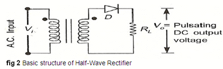
The a.c. voltage is applied to the rectifier circuit using step-down transformer, rectifying element i.e., p-n junction diode and the source of a.c. voltage, all connected in series. The a.c. voltage is applied to the rectifier circuit using a step-down transformer.
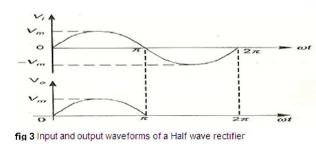
 V=Vm sin (wt) is the input to the rectifier circuit, where Vm is the peak value of secondary a.c. voltage.
Operation:
For the positive half-cycle of input a.c. voltage, the diode D is forward biased and hence it conducts. Now current flows in the circuit and there is a voltage drop across RL. The waveform of the diode current (or) load current is shown in fig 3.
For the negative half-cycle of input, the diode D is reverse biased and hence it does not
conduct. Now no current flows in the circuit i.e., i=0 and Vo=0. Thus, for the negative half- cycle no power is delivered to the load.
Analysis:
In the analysis of a HWR, the following parameters are to be analyzed.
- DC output current
- DC Output voltage
- R.M.S. Current
- R.M.S. voltage
- Rectifier Efficiency (η )
- Ripple factor (γ )
- Peak Factor
- % Regulation
- Transformer Utilization Factor (TUF)
- form factor
- o/p frequency
Let a sinusoidal voltage V be applied to the input of the rectifier. V=Vm sin (wt) where Vm is the maximum value of the secondary voltage. Let the diode be idealized to piece-wise linear approximation with resistance Rf in the forward direction i.e., in the ON state and Rr (=∞) in the reverse direction i.e., in the OFF state. Now the current ‘i’ in the diode (or) in the load resistance RL is given by i=im sin (wt)
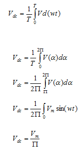
i) AVERAGE VOLTAGE
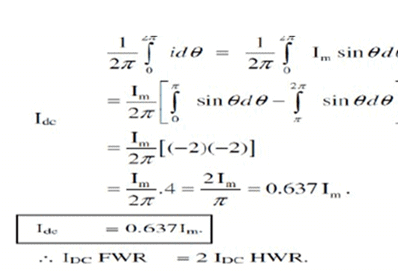
ii).AVERAGE CURRENT:

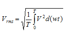
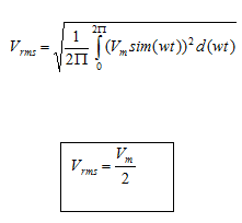
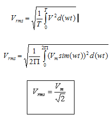
iii) R.M.S VOLTAGE:
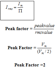
IV) R.M.S CURRENT
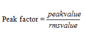
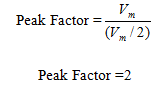
V) PEAK FACTOR:
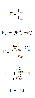
vii) Ripple Factor:
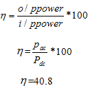
viii) Efficiency (η):
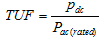
ix) Transformer Utilization Factor (TUF):
The d.c. power to be delivered to the load in a rectifier circuit decides the rating of the transformer used in the circuit. Therefore, transformer utilization factor is defined as
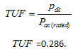
The value of TUF is low which shows that in a half-wave circuit, the transformer is not fully utilized.
If the transformer rating is 1 KVA (1000VA) then the half-wave rectifier can deliver 1000 X 0.286 = 286 watts to resistance load.
x) Peak Inverse Voltage (PIV):
It is defined as the maximum reverse voltage that a diode can withstand without destroying the junction. The peak inverse voltage across a diode is the peak of the negative half- cycle. For half-wave rectifier, PIV is Vm.
DISADVANTAGES OF HALF-WAVE RECTIFIER:
1. The ripple factor is high.
2. The efficiency is low.
3. The Transformer Utilization factor is low.
Because of all these disadvantages, the half-wave rectifier circuit is normally not used as a power rectifier circuit.
FULL-WAVE RECTIFIER (FWR):
A full-wave rectifier converts an ac voltage into a pulsating dc voltage using both half cycles of the applied ac voltage. In order to rectify both the half cycles of ac input, two diodes are used in this circuit. The diodes feed a common load RL with the help of a center-tap transformer. A center-tap transformer produces two sinusoidal waveforms of same magnitude and frequency but out of phase with respect to the ground in the secondary winding of the transformer. The full wave rectifier is shown in the fig 4 below.
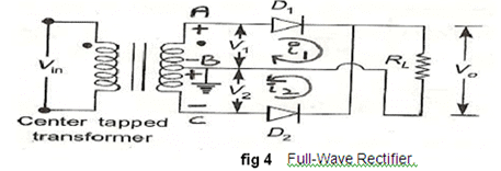
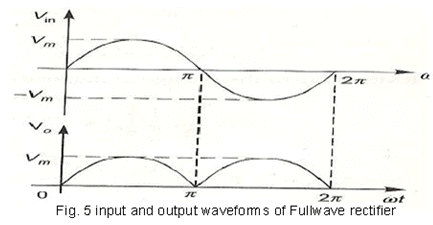
Fig. 5 shows the input and output wave forms of the circuit.
During positive half of the input signal, anode of diode D1 becomes positive and at the
same time the anode of diode D2 becomes negative. Hence D1 conducts and D2 does not
conduct. The load current flows through D1 and the voltage drop across RL will be equal to the input voltage.
During the negative half cycle of the input, the anode of D1 becomes negative and the anode of D2 becomes positive. Hence, D1 does not conduct and D2 conducts. The load current flows through D2 and the voltage drop across RL will be equal to the input voltage. It is to be noted that the load current flows in both the half cycles of ac voltage and in the same direction through the load resistance.
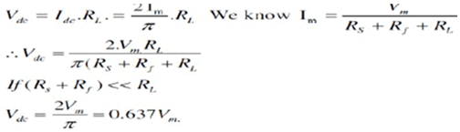
- AVERAGEVOLTAGE:
ii) AVERAGE CURRENT
iii) RMS VOLTAGE:
IV) RMS CURRENT

V) PEAK FACTOR:
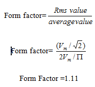
vi) FORM FACTOR
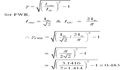
vii) Ripple Factor:
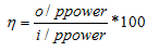
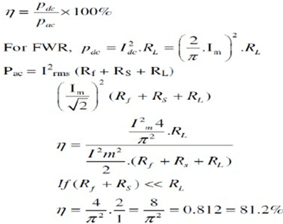
viii) Efficiency (η):
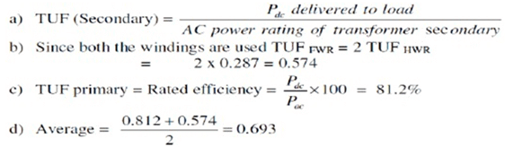
ix) Transformer Utilization Factor (TUF):
The d.c. power to be delivered to the load in a rectifier circuit decides the rating of the transformer used in the circuit. So, transformer utilization factor is defined as
x) Peak Inverse Voltage (PIV):
It is defined as the maximum reverse voltage that a diode can withstand without destroying the junction. The peak inverse voltage across a diode is the peak of the negative half- cycle. For full-wave rectifier, PIV is 2Vm.
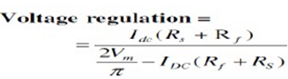
xi) % Regulation
Advantages
1) Ripple factor = 0.482 (against 1.21 for HWR)
2) Rectification efficiency is 0.812 (against 0.405 for HWR)
3) Better TUF (secondary) is 0.574 (0.287 for HWR)
4) No core saturation problem
Disadvantages:
- Requires center-tapped transformer.
BRIDGE RECTIFIER.
Another type of circuit that produces the same output waveform as the full wave rectifier circuit above, is the Full Wave Bridge Rectifier. This type of single phase rectifier uses four individual rectifying diodes connected in a closed loop "bridge" configuration to produce the desired output. The main advantage of this bridge circuit is that it does not require a special centre-tapped transformer, thereby reducing its size and cost. The single secondary winding is connected to one side of the diode bridge network and the load to the other side as shown below.
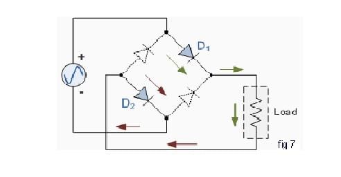
The Diode Bridge Rectifier
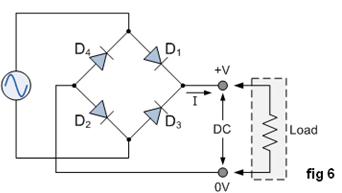
The four diodes labelled as D1 to D4 are arranged in "series pairs" with only two diodes conducting during each half cycle. During the positive half cycle of the supply, diodes D1 and D2 conduct in series while diodes D3 and D4 are reverse biased and the current flows through the load as shown below (fig 7).
The Negative Half-cycle
During the negative half cycle of the supply, diodes D3 and D4 conduct in series (fig 8), but diodes D1 and D2 switch "OFF" as they are now reverse biased. The current flowing through the load is in the same direction as before.
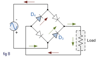
As the current flowing through the load is unidirectional, so the voltage developed across the load is also unidirectional (the same as for the previous two diode full-wave rectifier), therefore the average DC voltage across the load is 0.637Vmax. However in reality, during each half cycle the current flows through two diodes instead of just one so the amplitude of the output voltage is two voltage drops ( 2 x 0.7 = 1.4V ) less than the input Vmax amplitude. The ripple frequency is now twice the supply frequency (e.g. 100Hz for a 50Hz supply)
FAQs on Classification of Rectifiers - Electrical Engineering (EE)
| 1. What is a rectifier? |  |
| 2. What are the main types of rectifiers? | |
| 3. What is the working principle of a rectifier? | |
| 4. What is the role of filtering in rectifiers? | |
| 5. Can rectifiers handle high voltage and current levels? | |


Classification of Rectifiers - Electrical Engineering (EE)
,Classification of Rectifiers - Electrical Engineering (EE)
,Sample Paper
,Summary
,ppt
,Free
,video lectures
,Important questions
,Extra Questions
,shortcuts and tricks
,mock tests for examination
,MCQs
,Viva Questions
,Classification of Rectifiers - Electrical Engineering (EE)
,Previous Year Questions with Solutions
,Semester Notes
,Exam
,study material
,practice quizzes
,past year papers
,Objective type Questions
;


Classification of Rectifiers Free PDF Download
Importance of Classification of Rectifiers
Classification of Rectifiers Notes
Classification of Rectifiers Electrical Engineering (EE) Questions
Study Classification of Rectifiers on the App
|
© EduRev
|
Education Revolution
|


|


