Differentiator and Integrator Circuits | Analog and Digital Electronics - Electrical Engineering (EE) PDF Download
| Table of contents |

|
| What is Capacitance? |

|
| The Virtual Ground Effect |

|
| Integration |

|
| Formula to Determine Voltage Output |

|
By introducing electrical reactance into the feedback loops of an op-amp circuit, we can cause the output to respond to changes in the input voltage over time. Drawing their names from their respective calculus functions, the integrator produces a voltage output proportional to the product (multiplication) of the input voltage and time; and the differentiator (not to be confused with differential) produces a voltage output proportional to the input voltage’s rate of change.
What is Capacitance?
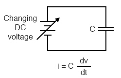
Capacitance can be defined as the measure of a capacitor’s opposition to changes in voltage. The greater the capacitance, the more the opposition. Capacitors oppose voltage change by creating current in the circuit: that is, they either charge or discharge in response to a change in the applied voltage. So, the more capacitance a capacitor has, the greater its charge or discharge current will be for any given rate of voltage change across it. The equation for this is quite simple:

The dv/dt fraction is a calculus expression representing the rate of voltage change over time. If the DC supply in the above circuit were steadily increased from a voltage of 15 volts to a voltage of 16 volts over a time span of 1 hour, the current through the capacitor would most likely be very small, because of the very low rate of voltage change (dv/dt = 1 volt / 3600 seconds). However, if we steadily increased the DC supply from 15 volts to 16 volts over a shorter time span of 1 second, the rate of voltage change would be much higher, and thus the charging current would be much higher (3600 times higher, to be exact). Same amount of change in voltage, but vastly different rates of change, resulting in vastly different amounts of current in the circuit.
To put some definite numbers to this formula, if the voltage across a 47 µF capacitor was changing at a linear rate of 3 volts per second, the current “through” the capacitor would be (47 µF)(3 V/s) = 141 µA.
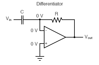
We can build an op-amp circuit which measures change in voltage by measuring current through a capacitor, and outputs a voltage proportional to that current:

The Virtual Ground Effect
The right-hand side of the capacitor is held to a voltage of 0 volts, due to the “virtual ground” effect. Therefore, current “through” the capacitor is solely due to change in the input voltage. A steady input voltage won’t cause a current through C, but a changing input voltage will.
Capacitor current moves through the feedback resistor, producing a drop across it, which is the same as the output voltage. A linear, positive rate of input voltage change will result in a steady negative voltage at the output of the op-amp. Conversely, a linear, negative rate of input voltage change will result in a steady positive voltage at the output of the op-amp. This polarity inversion from input to output is due to the fact that the input signal is being sent (essentially) to the inverting input of the op-amp, so it acts like the inverting amplifier mentioned previously. The faster the rate of voltage change at the input (either positive or negative), the greater the voltage at the output.
The formula for determining voltage output for the differentiator is as follows:

Rate-of-Change Indicators for Process Instrumentation
Applications for this, besides representing the derivative calculus function inside of an analog computer, include rate-of-change indicators for process instrumentation. One such rate-of-change signal application might be for monitoring (or controlling) the rate of temperature change in a furnace, where too high or too low of a temperature rise rate could be detrimental. The DC voltage produced by the differentiator circuit could be used to drive a comparator, which would signal an alarm or activate a control if the rate of change exceeded a pre-set level.
In process control, the derivative function is used to make control decisions for maintaining a process at setpoint, by monitoring the rate of process change over time and taking action to prevent excessive rates of change, which can lead to an unstable condition. Analog electronic controllers use variations of this circuitry to perform the derivative function.
Integration
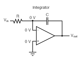
On the other hand, there are applications where we need precisely the opposite function, called integration in calculus. Here, the op-amp circuit would generate an output voltage proportional to the magnitude and duration that an input voltage signal has deviated from 0 volts. Stated differently, a constant input signal would generate a certain rate of change in the output voltage: differentiation in reverse. To do this, all we have to do is swap the capacitor and resistor in the previous circuit:

As before, the negative feedback of the op-amp ensures that the inverting input will be held at 0 volts (the virtual ground). If the input voltage is exactly 0 volts, there will be no current through the resistor, therefore no charging of the capacitor, and therefore the output voltage will not change. We cannot guarantee what voltage will be at the output with respect to ground in this condition, but we can say that the output voltage will be constant.
However, if we apply a constant, positive voltage to the input, the op-amp output will fall negative at a linear rate, in an attempt to produce the changing voltage across the capacitor necessary to maintain the current established by the voltage difference across the resistor. Conversely, a constant, negative voltage at the input results in a linear, rising (positive) voltage at the output. The output voltage rate-of-change will be proportional to the value of the input voltage.
Formula to Determine Voltage Output
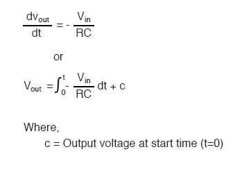
The formula for determining voltage output for the integrator is as follows:

One application for this device would be to keep a “running total” of radiation exposure, or dosage, if the input voltage was a proportional signal supplied by an electronic radiation detector. Nuclear radiation can be just as damaging at low intensities for long periods of time as it is at high intensities for short periods of time. An integrator circuit would take both the intensity (input voltage magnitude) and time into account, generating an output voltage representing total radiation dosage.
Another application would be to integrate a signal representing water flow, producing a signal representing total quantity of water that has passed by the flowmeter. This application of an integrator is sometimes called a totalizer in the industrial instrumentation trade.
|
137 videos|143 docs|71 tests
|
FAQs on Differentiator and Integrator Circuits - Analog and Digital Electronics - Electrical Engineering (EE)
| 1. What is capacitance and how does it relate to electrical engineering? |  |
| 2. What is the Virtual Ground Effect in integrator and differentiator circuits? |  |
| 3. How is integration used in electrical engineering circuits? |  |
| 4. What is the formula to determine the voltage output in differentiator circuits? |  |
| 5. How do differentiator and integrator circuits play a role in electrical engineering applications? |  |

|
Explore Courses for Electrical Engineering (EE) exam
|

|


