Digital Signal Processors | Embedded Systems (Web) - Computer Science Engineering (CSE) PDF Download

Instructional Objectives
After going through this lesson the student would learn
- Architecture of a Real time Signal Processing Platform
- Different Errors introduced during A-D and D-A converter stage
- Digital Signal Processor Architecture
- Difference in the complexity of programs between a General Purpose Processor and Digital Signal Processor
Pre-Requisite
Digital Electronics, Microprocessors
Introduction
Evolution of Digital Signal Processors
Comparative Performance with General Purpose Processor
Introduction
Digital Signal Processing deals with algorithms for handling large chunk of data. This branch identified itself as a separate subject in 70s when engineers thought about processing the signals arising from nature in the discrete form. Development of Sampling Theory followed and the design of Analog-to-Digital converters gave an impetus in this direction. The contemporary applications of digital signal processing was mainly in speech followed by Communication, Seismology, Biomedical etc. Later on the field of Image processing emerged as another important area in signal processing.
The following broadly defines different processor classes
- General Purpose - high performance
- Pentiums, Alpha's, SPARC
- Used for general purpose software
- Heavy weight OS - UNIX, NT
- Workstations, PC's
- Embedded processors and processor cores
- ARM, 486SX, Hitachi SH7000, NEC V800
- Single program
- Lightweight, real-time OS
- DSP support
- Cellular phones, consumer electronics (e. g. CD players)
- Microcontrollers
- Extremely cost sensitive
- Small word size - 8 bit common
- Highest volume processors by far
- Automobiles, toasters, thermostats, ...
A Digital Signal Processor is required to do the following Digital Signal Processing tasks in real time
- Signal Modeling
- Difference Equation
- Convolution
- Transfer Function
- Frequency Response
- Signal Processing
- Data Manipulation
- Algorithms Filtering
- Estimation
What is Digital Signal Processing?
Application of mathematical operations to digitally represented signals
- Signals represented digitally as sequences of samples
- Digital signals obtained from physical signals via transducers (e.g., microphones) and analog-to- digital converters (ADC)
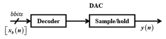
- Digital signals converted back to physical signals via digital-to-analog converters (DAC)
- Digital Signal Processor (DSP): electronic system that processes digital signals
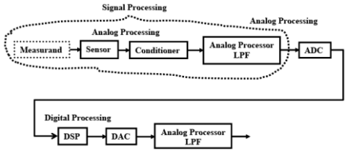
Fig. 7.1 The basic Signal Processing Platform
The above figure represents a Real Time digital signal processing system. The measurand can be temperature, pressure or speech signal which is picked up by a sensor (may be a thermocouple, microphone, a load cell etc). The conditioner is required to filter, demodulate and amplify the signal. The analog processor is generally a low-pass filter used for anti-aliasing effect. The ADC block converts the analog signals into digital form. The DSP block represents the signal processor. The DAC is for Digital to Analog Converter which converts the digital signals into analog form. The analog low-pass filter eliminates noise introduced by the interpolation in the DAC.
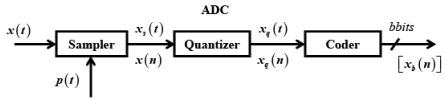
The performance of the signal processing system depends to the large extent on the ADC. The ADC is specified by the number of bits which defines the resolution. The conversion time decides the sampling time. The errors in the ADC are due to the finite number of bits and finite conversion time. Some times the noise may be introduced by the switching circuits.
Similarly the DAC is represented by the number of bits and the settling time at the output. A DSP tasks requires
- Repetitive numeric computations
- Attention to numeric fidelity
- High memory bandwidth, mostly via array accesses
- Real-time processing
And the DSP Design should minimize
- Cost
- Power
- Memory use
- Development time
Take an Example of FIR filtering both by a General Purpose Processor as well as DSP
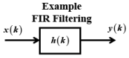
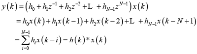
An FIR (Finite Impulse Response filter) is represented as shown in the following figure. The output of the filter is a linear combination of the present and past values of the input. It has several advantages such as:
- Linear Phase
- Stability
- Improved Computational Time
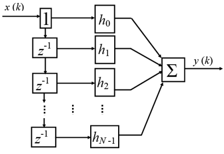
Fig. 7.3 Tapped Delay Line representation of an FIR filter
FIR filter on (simple) General Purpose Processor
loop:
lw x0, (r0)
lw y0, (r1)
mul a, x0,y0
add b,a,b
inc r0
inc r1
dec ctr
tst ctr
jnz loop
sw b,(r2)
inc r2
This program assumes that the finite window of input signal is stored at the memory location starting from the address specified by r1 and the equal number filter coefficients are stored at the memory location starting from the address specified by r0. The result will be stored at the memory location starting from the address specified by r2. The program assumes the content of the register b as 0 before the start of the loop.
lw x0, (r0)
lw y0, (r1)
These two instructions load x0 and y0 registers with values from the memory location specified by the registers r0 and r1 with values x0 and y0
mul a, x0,y0
This instruction multiplies x0 with y0 and stores the result in a.
add b,a,b
This instruction adds a with b (which contains already accumulated result from the previous operation) and stores the result in b.
inc r0
inc r1
dec ctr
tst ctr
jnz loop
The above portion of the program increment the registers to point to the next memory location, decrement the counters, to see if the filter order has been reached and tests for 0. It jumps to the start of the loop.
sw b,(r2)
inc r2
This stores the final result and increments the register r2 to point to the next location.
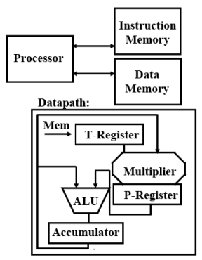
Let us see the program for an early DSP TMS32010 developed by Texas
Instruments in 80s. It has got the following features
- 16-bit fixed-point
- Harvard architecture separate instruction and data memories
- Accumulator
- Specialized instruction set Load and Accumulate
- 390 ns Multiple-Accumulate(MAC)
TI TMS32010 (Ist DSP) 1982
The program for the FIR filter (for a 3rd order) is given as follows
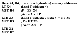
• Two instructions per tap, but requires unrolling
; for comment lines
LT X4 Loading from direct address X4
MPY H4 Multiply and accumulate
LTD X3 Loading and shifting in the data points in the memory
The advantages of the DSP over the General Purpose Processor can be written as Multiplication and Accumulation takes place at a time. Therefore this architecture supports filtering kind of tasks. The loading and subsequent shifting is also takes place at a time.
II. Questions
1. Discuss the different errors introduced in a typical real time signal processing systems.
Answers
Various errors are in
ADC
i. Sampling error
ii. Quantization
iii. Coding
Algorithm
iv. in accurate modeling
v. Finite word length
vi. Round of errors
vii. Delay due to finite execution time of the processor
DAC
viii. Decoding
ix. Transients in sampling time
|
47 videos|77 docs|65 tests
|
FAQs on Digital Signal Processors - Embedded Systems (Web) - Computer Science Engineering (CSE)
| 1. What is a digital signal processor (DSP)? |  |
| 2. How does a digital signal processor differ from a general-purpose microprocessor? | |
| 3. What are the common applications of digital signal processors? | |
| 4. How do digital signal processors achieve real-time processing of signals? | |
| 5. What are the advantages of using digital signal processors over software-based signal processing? | |


Exam
,Summary
,past year papers
,shortcuts and tricks
,MCQs
,video lectures
,Objective type Questions
,Digital Signal Processors | Embedded Systems (Web) - Computer Science Engineering (CSE)
,Important questions
,Digital Signal Processors | Embedded Systems (Web) - Computer Science Engineering (CSE)
,Digital Signal Processors | Embedded Systems (Web) - Computer Science Engineering (CSE)
,Free
,Semester Notes
,Sample Paper
,Previous Year Questions with Solutions
,Viva Questions
,Extra Questions
,mock tests for examination
,study material
,ppt
,practice quizzes
;


Digital Signal Processors Free PDF Download
Importance of Digital Signal Processors
Digital Signal Processors Notes
Digital Signal Processors Computer Science Engineering (CSE) Questions
Study Digital Signal Processors on the App
|
© EduRev
|
Education Revolution
|


|


