Electromagnetic Waves - 2 - Electronics and Communication Engineering (ECE) PDF Download

Propagation of Electromagnetic Waves in a Conducting Medium
We will consider a plane electromagnetic wave travelling in a linear dielectric medium such as air along the z direction and being incident at a conducting interface. The medium will be taken to be a linear medium. So that one can describe the electrodynamics using only the E and H vectors. We wish to investigate the propagation of the wave in the conducting medium.
As the medium is linear and the propagation takes place in the infinite medium, the vectors  and
and  are still mutually perpendicular. We take the electric field along the x direction, the magnetic field along the y- dirrection and the propagation to take place in the z direction. Further, we will take the conductivity to be finite and the conductor to obey Ohm’s law,
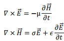
  Consider the pair of curl equations of Maxwell.
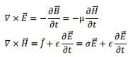
Let us take  to be respectively in x, y and z direction. We the nhave,
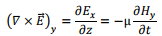
i.e.,
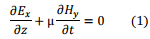
and
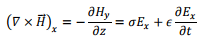
i.e.
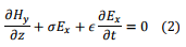
We take the time variation to be harmonic  so that the time derivative is equivalent to a multiplication by
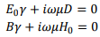
  . The pair of equations (1) and (2) can then be written as
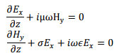
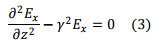
We can solve this pair of coupled equations by taking a derivative of either of the equations with respect to z and substituting the other into it,
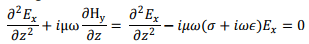
Define, a complex constan γ through
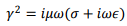
in terms of which we have,
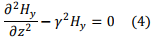
In an identical fashion, we get
Solutions of (3) and (4) are well known and are expressed in terms of hyperbolic functions,
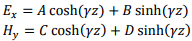
where A, B, C and D are constants to be determined. If the values of the electric field at z=0 is E0 and that of the magnetic field at z=0 is H0 we have A E0 and C =H0.
In order to determine the constants B and D, let us return back to the original first order equations (1) and (2)
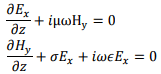
Substituting the solutions for E and H

This equation must remain valid for all values of z, which is possible if the coefficients of sinh and cosh terms are separately equated to zero,
The former gives,
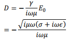
where
Likewise, we get,

Substituting these, our solutions for the E and H become,
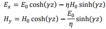
The wave is propagating in the z direction. Let us evaluate the fields when the wave has reached 
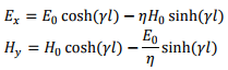
If ℓ is large, we can approximate
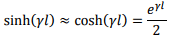
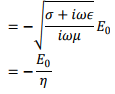
we then have,
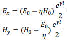
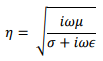
The ratio of the magnitudes of the electric field to magnetic field is defined as the “characteristic impedance” of the wave
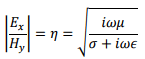
Suppose we have lossless medium, σ=0, i.e. for a perfect conductor, the characteristic impedance is

If the medium is vacuum,  gives η≈377Ω. The characteristic impedance, as the name suggests, has the dimension of resistance.
In this case, 
Let us look at the full three dimensional version of the propagation in a conductor. Once again, we start with the two curl equations,
Take a curl of both sides of the first equation,
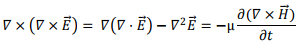
As there are no charges or currents, we ignore the divergence term and substitute for the curl of H from the second equation,
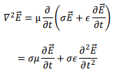
We take the propagating solutions to be
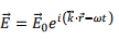
so that the above equation becomes,
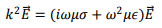
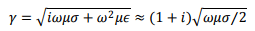
so that we have, the complex propagation constant to be given by
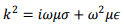
so that
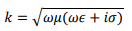
k is complex and its real and imaginary parts can be separated by standard algebra,
we have
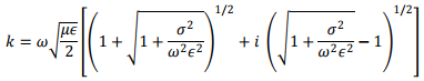
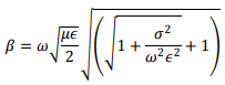
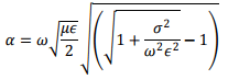
Thus the propagation vector β and the attenuation factor α are given by
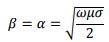
The ration  determines whether a material is a good conductor or otherwise. Consider a good conductor for which σ>> ω∈.For this case, we have,
The speed of electromagnetic wave is given by

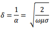
The electric field amplitude diminishes with distance as  The distance to which the field penetrates before its amplitude diminishes be a factor e-1 is known as the “skin depth” , which is given by
The wave does not penetrate much inside a conductor. Consider electromagnetic wave of frequency 1 MHz for copper which has a conductivity of approximately  Substituting these values, one gets the skin depth in Cu to be about 0.067 mm. For comparison, the skin depth in sea water which is conducting because of salinity, is about 25 cm while that for fresh water is nearly 7m. Because of small skin depth in conductors, any current that arises in the metal because of the electromagnetic wave is confined within a thin layer of the surface.
Reflection and Transmission from interface of a conductor
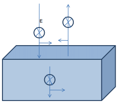
Consider an electromagnetic wave to be incident normally at the interface between a dielectric and a conductor. As before, we take the media to be linear and assume no charge or current densities to exist anywhere. We then have a continuity of the electric and the magnetic fields at the interface so that

The relationships between the magnetic field and the electric field are given by
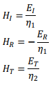
the minus sign in the second relation comes because of the propagation direction having been reversed on reflection.
Solving these, we get,
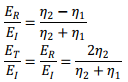
The magnetic field expressions are given by interchanging η1 and η2 in the above expressions.
Let us look at consequence of this. Consider a good conductor such as copper. We can see that η2 is a small complex number. For instance, taking the wave frequency to be 1 MHz and substituting conductivity of Cu to be  we can calculate η2 to be approximately
 whereas the vacuum impedance η1= 377 Ω. This implies
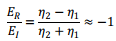
which shows that a good metal is also a good reflector. On the other hand, if we calculate the transmission coefficient we find it to be substantially reduced, being only about 
For the transmitted magnetic field, the ratio  is approximately +2. Though E is reflected with a change of phase, the magnetic field is reversed in direction but does not undergo a phase change. The continuity of the magnetic field then requires that the transmitted field be twice as large.
Surface Impedance
As we have seen, the electric field is confined to a small depth at the conductor interface known as the skin depth. We define surface impedance as the ratio of the parallel component of electric field that gives rise to a current at the conductor surface,

where ks is the surface current density.
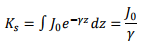
Assuming that the current flows over the skin depth, one can write, for the current density, (assuming no reflection from the back of this depth)

Since the current density has been taken to decay exponentially, we can extend the integration to infinity and get
The current density at the surface can be written as  For a good conductor, we have,
Thus
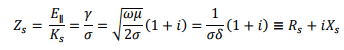
where the surface resistance Rs and surface reactance Xs are given by

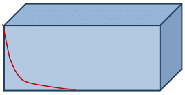
The current profile at the interface is as shown.
Tutorial Assignment
- A 2 GHz electromagnetic propagates in a non-magnetic medium having a relative permittivity of 20 and a conductivity of 3.85 S/m. Determine if the material is a good conductor or otherwise. Calculate the phase velocity of the wave, the propagation and attenuation constants, the skin depth and the intrinsic impedance.
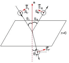
- An electromagnetic wave with its electric field parallel to the plane of incidence is incident from vacuum onto the surface of a perfect conductor at an angle of incidence θ. Obtain an expression for the total electric and the magnetic field.
Solutions to Tutorial Assignments
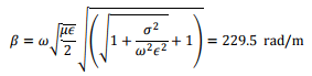
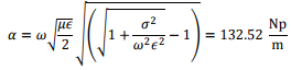
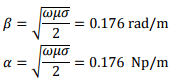
1. One can see that  The ratio of conductivity σ ω∈ is 1.73 which says it is neither a good metal nor a good dielectric. The propagation constant β and the attenuation constant α are given by,
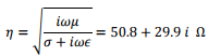
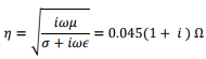
The intrinsic impedance is
The phase velocity is 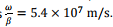
The skin depth is 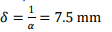
2. The case of p polarization is shown.
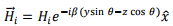
Let the incident plane be y-z plane. Let us look at the magnetic field. We have, since both the incident and the reflected fields are in the same medium,

Let us write the incident magnetic field as
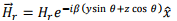
The reflected magnetic field is given by
Since the tangential components of the electric field is continuous, we have,
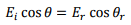
As  we have
  and consequently,
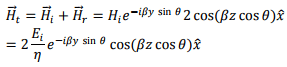
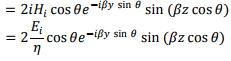
  Thus the total magnetic field can be written as
The electric field has both y and z components,
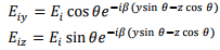
The reflected electric field also has both components,
Adding these two the total electric field, has the following components,
Self Assessment Questions
- For electromagnetic wave propagation inside a good conductor, show that the electric and the magnetic fields are out of phase by 450 .
- A 2 kHz electromagnetic propagates in a non-magnetic medium having a relative permittivity of 20 and a conductivity of 3.85 S/m. Determine if the material is a good conductor or otherwise. Calculate the phase velocity of the wave, the propagation and attenuation constants, the skin depth and the intrinsic impedance.
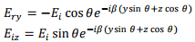
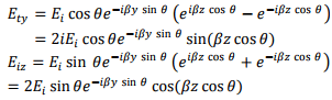
- An electromagnetic wave with its electric field perpendicular to the plane of incidence is incident from vacuum onto the surface of a perfect conductor at an angle of incidence θ. Obtain an expression for the total electric and the magnetic field.
Solutions to Self Assessment Questions
1. From the text, we see that the ratio of electric field to magnetic field is given by
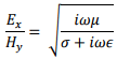
For a good conductor, we can approximate this by 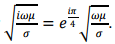
2. One can see that  The ratio of conductivity
 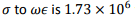 which says it is r a good metal. The propagation constant β and the attenuation constant α are given by,
The intrinsic impedance is
The phase velocity is 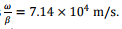
The skin depth is 
3. The direction of electric and magnetic field for s polarization is as shown below.
Let the incident plane be y-z plane. The incident electric field is
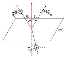
taken along the x direction and is given by
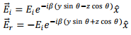
The minus sign comes because at z=0, for any y, the tangential component of the electric field must be zero.
The total electric field is along the x direction and is given by the sum of the above,
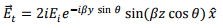
which is a travelling wave in the y direction but a standing wave in the z direction. Since the wave propagates in vacuum, we have,

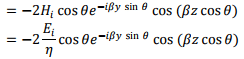
The magnetic field has both y and z components.


FAQs on Electromagnetic Waves - 2 - Electronics and Communication Engineering (ECE)
| 1. What are electromagnetic waves? |  |
| 2. What are the different types of electromagnetic waves? | |
| 3. How are electromagnetic waves produced? | |
| 4. What are the applications of electromagnetic waves? | |
| 5. Can electromagnetic waves be harmful to human health? | |


Top Courses for Electronics and Communication Engineering (ECE)
Electromagnetic Waves - 2 - Electronics and Communication Engineering (ECE)
,Summary
,past year papers
,Electromagnetic Waves - 2 - Electronics and Communication Engineering (ECE)
,Important questions
,Previous Year Questions with Solutions
,Free
,Electromagnetic Waves - 2 - Electronics and Communication Engineering (ECE)
,Semester Notes
,shortcuts and tricks
,Exam
,Viva Questions
,Objective type Questions
,Extra Questions
,ppt
,study material
,video lectures
,MCQs
,Sample Paper
,mock tests for examination
,practice quizzes
;


Electromagnetic Waves - 2 Free PDF Download
Importance of Electromagnetic Waves - 2
Electromagnetic Waves - 2 Notes
Electromagnetic Waves - 2 Electronics and Communication Engineering (ECE) Questions
Study Electromagnetic Waves - 2 on the App
|
© EduRev
|
Education Revolution
|


|


