Electromagnetic Waves | Physics for Grade 12 PDF Download
The Electromagnetic Spectrum
Properties of Electromagnetic Waves
- Visible light is just one part of a much bigger spectrum: The Electromagnetic Spectrum
- All electromagnetic waves have the following properties in common:
- They are all transverse waves
- They can all travel in a vacuum
- They all travel at the same speed in a vacuum (free space) — the speed of light
- The speed of light in air is approximately the same as in a vacuum
 Oscillating electric and magnetic fields in an electromagnetic wave
- These transverse waves consist of electric and magnetic fields oscillating at right angles to each other and to the direction in which the wave is travelling (in 3D space)
- Since they are transverse, all waves in this spectrum can:
- Reflect
- Refract
- Diffract
- Be polarised
- Produce interference patterns
The Electromagnetic Spectrum
- The electromagnetic spectrum (EM) is arranged in a specific order based on the wavelengths or frequencies
- This order is shown in the diagram below from longest wavelength (lowest frequency) to shortest wavelength (highest frequency)
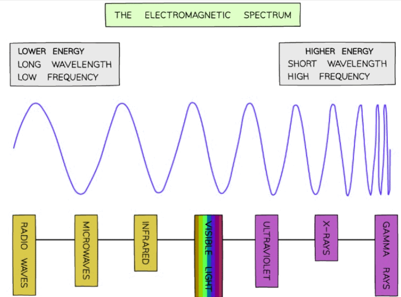 Energy, wavelength and frequency for each part of the electromagnetic spectrum
- The higher the frequency, the higher the energy of the radiation
- Radiation with higher energy is highly ionising and is harmful to cells and tissues causing cancer (e.g. UV, X-rays, Gamma rays)
Uses of EM Waves
- Electromagnetic waves have a large number of uses
- The main uses are summarised in the table below:
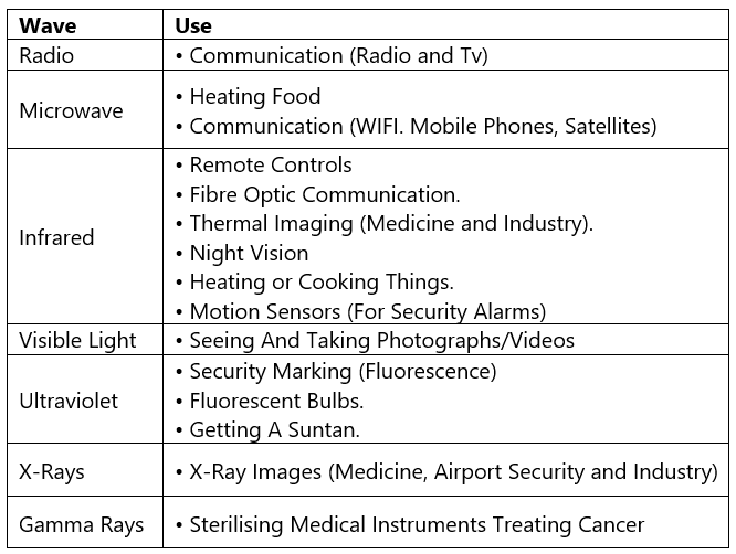
Wavelengths in the Electromagnetic Spectrum
The approximate wavelengths in a vacuum of each radiation are listed in the table below:
Table of EM spectrum wavelengths and frequencies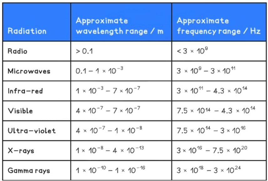
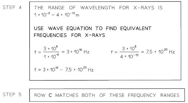
- To alternatively find the range of frequencies, convert the wavelengths using the wave equation: c = fλ where c is the speed of light: 3.0 × 10⁸ m s-1
Example: A is a source emitting microwaves and B is a source emitting X-rays. The table suggests the frequencies for A and B.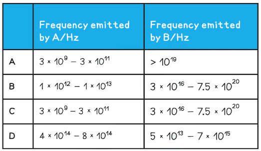
Which row is correct?
Ans. C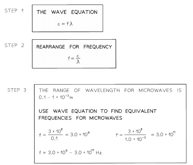
Polarisation
Polarisation is when:
- Particle oscillations occur in only one of direction perpendicular to the direction of wave propagation
Polarisation can only occur in transverse waves
- This is because electromagnetic transverse waves are oscillating electric and magnetic fields in any plane perpendicular to the propagation direction
When transverse waves are polarised, this means:
- Vibrations are restricted to one direction
- These vibrations are still perpendicular to the direction of propagation / energy transfer
The difference between unpolarised and polarised waves is shown in the diagram below:
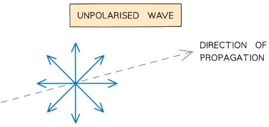
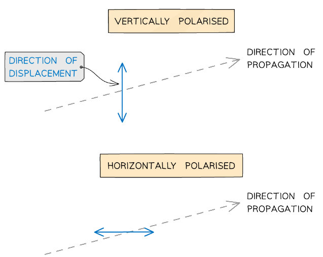 Diagram showing the displacement of unpolarised and polarised transverse waves
- Light from the sun or a lightbulb, or any that hasn't gone through a polarising filter is unpolarised
- Longitudinal waves (e.g. sound waves) cannot be polarised
- This is because they oscillate parallel to the direction of travel
- Waves can be polarised through a polariser such as a polarising filter (light) or metal grilles (microwaves)
- This only allows oscillations in a certain plane to be transmitted
- This is called a plane-polarised wave
Polarising Filters
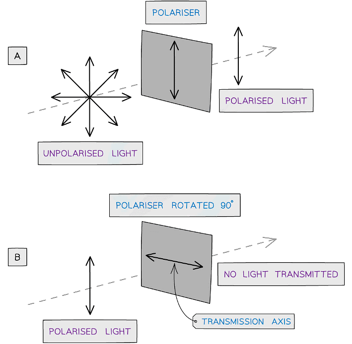 Diagram showing an unpolarised and polarised wave travelling through polarising filters
- Diagram A shows:
Only unpolarised waves can be polarised - Diagram B shows:
When a polarised wave passes through a filter with a transmission axis perpendicular to the wave, none of the wave will pass through - Light can also be polarised through reflection, refraction and scattering
Metal Grilles
- A metal grille is similar to a polarising filter, and commonly used for polarising microwaves
- Microwaves are electromagnetic waves with a longer wavelength than visible light
- By convention, the direction of polarisation is only the direction of the electric field propagation (rather than magnetic)
- A metal grille is different from a polarising filter
- The free electrons moving in the metal bar can cancel out the electric field in the same direction as the grille and completely absorb it
- Thus the horizontal electric field passes if the grilles are positioned vertically and vice versa
- This is the opposite of what happens in a polarising filter
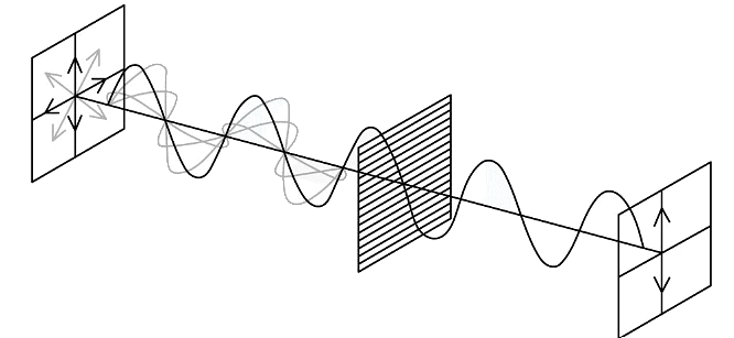 A metal grille is used to polarise a microwave
Investigating Light Intensity with Two Polarisers
If an unpolarised light source is placed in front of two identical polarising filters, A and B, with their transmission axes parallel:
- Filter A will polarise the light in a certain axis
- All of the polarised light will pass through filter B unaffected
- In this case, the maximum intensity of light is transmitted
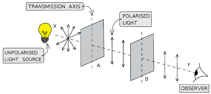 When both polarisers have the same transmission axis, the intensity of the transmitted light is at its maximum
- As the polarising filter B is rotated anticlockwise, the intensity of the light observed changes periodically depending on the angle B is rotated through
- When A and B have their transmission axes perpendicular to each other:
- Filter A will polarise the light in a certain axis
- This time none of the polarised light will pass through filter B
- In this case, the minimum intensity of light is transmitted
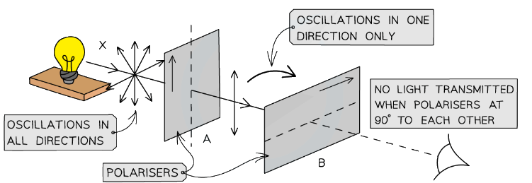 When one of the polarisers is rotated through 90°, the intensity of the transmitted light drops to zero
- The resulting graph of the light intensity with angle, as the second polariser is rotated through 360°, looks as follows:
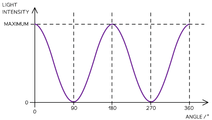 Graph showing how the intensity of the transmitted beam varies with the angle between the transmission axes of the two polarisers
Example: Which statement below describes a situation in which polarisation should happen?
(a) Radio waves pass through a metal grid
(b) Surface water waves are diffracted
(c) Sound waves are reflected
(d) Ultrasound waves pass through a metal grid
Ans. a
- Radio waves are transverse waves - they can be polarised by a metal grid so only the waves that fit through the grid will be transmitted, therefore, A is correct
- B cannot be correct as waves are not polarised when diffracted, but are polarised only when reflected, refracted or scattered
- C & D cannot be correct as polarisation only occurs for transverse waves, therefore, C & D can be ruled out as sound and ultrasound are both longitudinal waves
Observing Polarising Effects
Observing Polarisation of Microwaves
- A microwave transmitter can emit naturally polarised waves with a wavelength of around 3 cm
- To check whether the microwaves are polarised, place a microwave receiver in front of the transmitter and rotate about the axis through them
- The signal, which is detected using an ammeter or audio amplifier and loudspeaker will rise and fall with intensity as the receiver is rotated
- When the transmitter and the polarisation axis of the receiver are perpendicular to each other, the signal will be 0
- When the receiver has a maximum signal, a metal grille can be placed between the transmitter and receiver, acting as a second polariser
- When the grille is rotated (for example, in 10° increments), the signal varies and is 0 when the metal rods are aligned with the electric field vector of the emitted microwaves
- If the microwave transmitter is producing vertically plane-polarised radiation:
- If the bars of the metal grille are horizontally orientated, very few of
- the microwaves will be absorbed and the ammeter will read a high value
- If the bars of the metal grille are vertically orientated, all of the
- microwaves will be absorbed because they are vertically plane-
- polarised and the ammeter will read 0
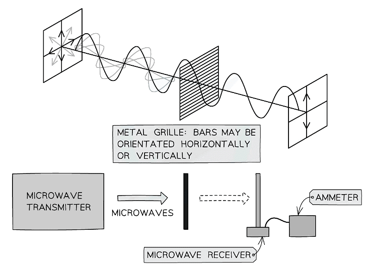 The polarisation of microwaves can be detected using a transmitter and receiver
- Radio and television services are broadcast either horizontally-polarised or vertically-polarised
- Therefore, the reception aerial needs to be mounted flat (horizontal), or on its side (vertical),
- The particular orientation of an aerial will depend on the transmitter it is pointing towards and the polarity of the services being broadcast
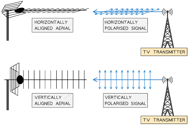 Broadcasting towers always transmit either vertically or horizontally polarised signals. This is why aerials must be positioned accordingly otherwise they won't pick up the TV signal correctly
Observing Polarisation of Light
- Polarisation of light can be observed by looking through a polarising filter at different light sources (such as the Sun, a light bulb or a laptop screen)
- This can be with two filters aligned at different angles to each other
- As one of the filters is rotated through different angles with respect to the other, the intensity of transmitted light passing through rises and falls
- It can also be observed by looking through a single polarising filter at light reflected at a shallow angle from water, such as a pond, or from shiny surfaces in the lab
- Rotating the polarising filter shows the reflected image become dimmer and brighter again
- One use of this is in photography
 As well as giving a cool look to photographs, polaroid filters are extremely useful for reducing glare in photos and snapping pictures of objects underwater
|
142 videos|312 docs|132 tests
|


