Error Analysis & Oscilloscope | Electrical and Electronic Measurements - Electrical Engineering (EE) PDF Download
Errors Analysis
- Errors: It is defined as the deviation of the true value from the desired value.
Classification of Errors
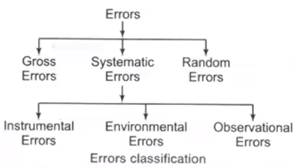
- Gross Errors
- Mistake by observer
- Reading and recording error
- Calculation mistake
- Systematic Errors
These errors occur due to short comings of the instruments such as defective or worn parts or aging or effects of the environment on the instrument. Systematic errors are classified as
(i) Instrumental Errors
These errors arises due to following reasons
(a) Due to the inherent defect in the instrument.
(b) Due to mishandling or misuse of the instrument.
(c) Due to loading effect.
(ii) Environmental Errors
These errors occur due to change in the environmental parameters such as temperature, humidity, pressure etc.
(iii) Observational Errors
The most common errors is the parallax error introduced in reading a meter scale and the error of estimation. - Random Errors
(i) Absolute Errors/Limiting Errors/Static Errors
It is the difference between measured value and a true value of a quantity.
δA = Am - AT
where, Am = Measured value or actual value
AT = True value or nominal value
(ii) Relative Static Errors
It is the ratio of absolute static error (δA) to true value (AT) of the quantity under measurement.
Static Correction
δC = AT - Am = -δA
(iii) Percentage Error
The relative error may be quoted as a fraction e.g., 5 parts in 1000 or may be expressed as a percentage.
Shortcut
Combination of Quantities With Limiting Errors
The following cases will be considered
- Case 1 Sum of Quantities
Let A = A1+A2+A3+...+An
Where, δA1, δA2... = relative increment in quantity A1, A2….. relative limiting error in quantity A1, A2…….
δA/A = relative limiting error in A - Case 2 Difference of Quantities
Let
A = A1 - A2
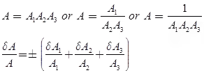
- Case 3 Multiplication or Quotient of More than Two Quantities
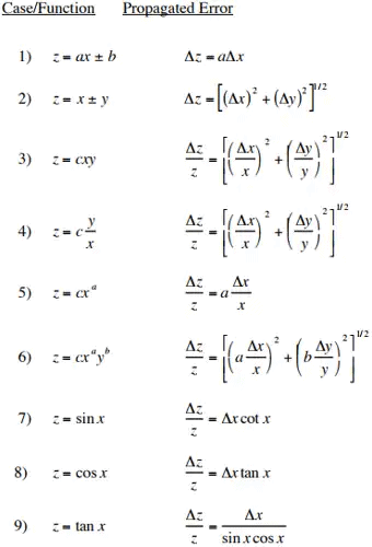
- Case 4 Composite Errors

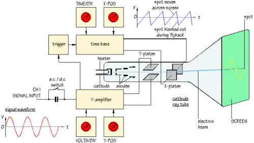
The Cathode Ray Oscilloscope
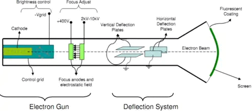
The main part of the C.R.O. is a highly evacuated glass tube housing parts which generate a beam of electrons, accelerates them, shapes them into a narrow beam, and provides external connections to the sets of plates described m above for changing the direction of the beam.
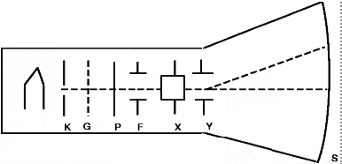
Component of C.R.O
- K, an indirectly heated cathode which provides a source of electrons for the beam by “boiling” them out of the cathode.
- P, the anode (or plate) which is circular with a small central hole. The potential of P creates an electric field which accelerates the electrons, some of which emerge from the hole as a fine beam. This beam lies along the central axis of the tube.
- G, the grid. Controlling the potential of the grid controls the number of electrons for the beam, and hence the intensity of the spot on the screen where the beam hits.
- F, the focusing cylinder. This aids in concentrating the electron beam into a thin straight line much as a lens operates in optics.
- X, Y, deflection plate pairs. The X plates are used for deflecting the beam left to right (the x-direction) by means of the “ramp” voltage.The Y plates are used for deflection of the beam in the vertical direction. Voltages on the X and Y sets of plates determine where the beam will strike the screen and cause a spot of light.
- S, the screen. This is coated on the inside with a material which fluoresces with green light (usually) where the electrons are striking.
As well as this tube, there are several electronic circuits required to operate the tube, all within the C.R.O. along with the tube explained below
- A power supply, operated from the 110 volts 60 cycle per second electrical “mains”. This supply provides all the voltages required for the different circuits within the C.R.O. for operation of the tube.
- A “sawtooth”, or “ramp” signal generator which makes the spot move left to right on the screen. External controls for this circuit allow variation of the sweep width, and the frequency of the sweep signal. Because of the persistence of our vision, this sweep is often fast enough that what we see on the screen is a continuous horizontal line.
- Amplifiers for the internally generated ramp signal, and for the “unknown” signal which we hook up to the C.R.O. for the purpose of displaying it.
- Shift devices which allow us to control the mean position of the beam; up or down, or left to right.
- The synchronizer circuit. This circuit allows us to synchronize the “unknown” signal with the ramp signal such that the resulting display is a nice clear signal like a snapshot of the unknown voltage vs. time.
CRO (Cathode Ray Oscilloscope) and Q-meter
CRO is a device which provides accurate time and amplitude of voltage signals over a wide range of frequencies.
- Deflection of Electron Beam
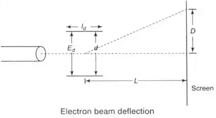
- Deflection

Where, L = distance between screen and the center of deflecting plates (m)
Id = length of deflecting plates (m)
Ed = potential between deflecting plates (V)
d = distance between deflecting plates (m)
Ea = voltage of pre-accelerating anode (V) - Deflection Sensitivity

- Deflection Factor

- Velocity of Electron Beam

Where, e = charge of electron = 16 × 10-19 C
m = mass of electron = 9.1 × 10⁻³¹ kg - Electrostatic Deflection
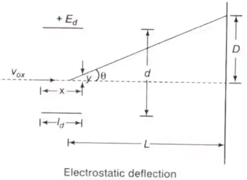

Where, y = displacement in y-direction (m)
e = charge of an electron (C)
m = mass of electron (kg)
x = displacement in X-direction (m)
Ey = electric field intensity in y-direction (V/m)
Vox = velocity of electron when entering in the fields of deflecting plates (m/s) - Frequency limit of CRO

Where, Vox = velocity of the electron beam in X-direction before it enters in deflecting plates
Id = length of vertical deflection plates - Rising Time of Vertical Amplifier

Where, BW = Bandwidth of oscilloscope (CRO)
Digital Storage Oscilloscope
- A digital storage oscilloscope is a special kind of storage oscilloscope that stores the input signal for years and displays it on a CRT screen when desired. Digital storage oscilloscope (DSO) is totally reversed to the working of analog storage oscilloscope. In the analog storage (ASO)oscilloscope the input signals are stored in mesh storage and whenever the signal display is needed the electron beam(or)electron gun is activated which hits the mesh storage passing through a horizontal amplifier and finally displays the signal on CRT screen. The stored signal can be used to display for up to few days as the signal has a tendency to fade away. In DSO the operation and working are totally different from that of ASO.
- In DSO the signals are stored in digital form rather than in analog form. The conversion of analog signals into digital/binary form can be achieved through Analog to digital conversion(ADC) technique. The converted signal is then stored in memory which acts as a storage unit in DSO. whenever the signal is needed to display on CRT the digital signal is reconstructed to analog form with the Digital to analog conversion (DAC) technique. The below figure is the block diagram of DSO.
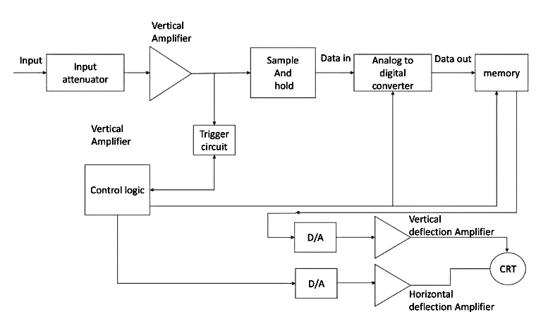
When an analog signal is given as an input it passes through an attenuator circuit where the unwanted noise signals are attenuated and this clean signal is applied to a vertical amplifier which performs the sampling and converts the input into digital. The digitally converted analog signal is stored in memory, which we can use as many times as we want to display on CRT. And coming to control logic it controls the ADC(Analog to Digital converter) conversion and deflection amplifiers. Both vertical and horizontal deflection amplifiers are connected to a DAC(Digital to Analog converter) which deflects the beam of electrons and so the trace on the CRT screen. This is the working of DSO.
Advantages of DSO- DSO is very easy to use and also allows for automation.
- we can store more than one input signal at a time which we can’t do in ASO.
- DSO can display much better-quality images.
- DSO is comparably cheaper than ASO.
- DSO can be used in the visual representation of radar targets.
- DSO can be used to measure AC and DC voltages and currents.
- DSO can be used in telecommunications.
- DSO is used as a monitoring device
- In the nuclear field, scientists use DSO to study environmental changes in absence of terrestrial/cellular signals.
DSO is an instrument used to display and analyze electronic signals.It draws waveforms or a graph of an instantaneous signal voltage against time.
|
48 videos|57 docs|22 tests
|
FAQs on Error Analysis & Oscilloscope - Electrical and Electronic Measurements - Electrical Engineering (EE)
| 1. What is a cathode ray oscilloscope? |  |
| 2. How does a cathode ray oscilloscope work? |  |
| 3. What are the main applications of a cathode ray oscilloscope? |  |
| 4. What are some common errors or sources of error when using a cathode ray oscilloscope? |  |
| 5. How can I minimize errors when using a cathode ray oscilloscope? |  |


