Error Detection & Correction Code


Introduction
Error detection and correction codes are essential in reliable digital communication and storage. When binary data is transmitted from a sender to a receiver over a noisy channel, noise may flip one or more bits (0 → 1 or 1 → 0). It is not always possible to avoid such interference, but by adding redundancy at the sender and using suitable algorithms at the receiver, most errors can be detected and many can be corrected, allowing recovery of the original data.
Error detection codes
Error detection codes are schemes that add redundancy to the original bitstream so that the receiver can determine whether the received bits have been corrupted. The sender encodes the message before transmission; the receiver decodes and checks the redundancy to detect the presence of errors with high probability.
- Purpose: Detect whether the received data contains errors introduced during transmission or storage.
- Method: Append extra bits (redundant bits) or compute summaries of the data that allow the receiver to verify integrity.
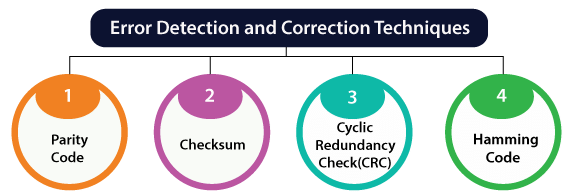
- Typical techniques: Parity, Checksum and CRC (Cyclic Redundancy Check).
- Limitation: Error detection alone does not correct errors. If an error is detected, further action (request for retransmission or higher-layer recovery) is needed unless error correction is also provided.
Parity code
Parity is the simplest error-detection code. One parity bit is appended to a block of data bits. Two common conventions are used:
- Even parity: parity bit chosen so that the total number of 1s in the block (data bits plus parity bit) is even.
- Odd parity: parity bit chosen so that the total number of 1s in the block is odd.
Properties and limitations:
- Parity detects any odd number of bit errors (1, 3, 5, ...) in the block.
- Parity fails to detect an even number of bit errors (2, 4, ...) because the parity of the block remains unchanged.
- Parity is low-overhead but offers limited protection; it is commonly used where simple integrity checks are sufficient or as an additional layer (for example, overall parity in memory modules).
Other detection techniques
- Checksum: The message is divided into fixed-size words, those words are added (often using one's complement arithmetic), and the complement of the sum is sent as the checksum. Common in transport protocols (e.g., older IP/TCP/UDP checksums) and file-transfer utilities.
- Cyclic Redundancy Check (CRC): The message bits are treated as coefficients of a polynomial M(x). A generator polynomial G(x) of degree r is chosen. The transmitter appends r zero bits, divides M(x)·x^r by G(x) and appends the remainder R(x). The receiver divides the received polynomial by G(x); a non-zero remainder indicates an error. CRCs are widely used because they detect burst errors effectively and can be implemented efficiently in hardware.
Error correction codes
Error correction codes (ECC) add structured redundancy so that the receiver can not only detect but also correct certain errors without retransmission. ECCs are designed by specific algorithms that allow locating corrupted bit positions and determining their original values.
- Block codes: Messages are divided into fixed-size blocks. Redundant parity bits are computed for each block and appended to form a codeword. The set of all valid codewords constitutes the code.
- Convolutional codes: The encoder processes a data stream of arbitrary length and produces parity symbols by applying Boolean functions over sliding windows of the input stream. The output is streamed continuously and is suitable for real-time or streaming channels.
Fundamental concepts for block codes
- Codeword: An n-bit sequence consisting of k information bits and r = n - k parity bits, denoted an (n, k) code.
- Hamming distance: The Hamming distance between two binary vectors is the number of positions in which they differ. The minimum Hamming distance dmin of a code is the smallest Hamming distance between any pair of distinct codewords.
- Error-detection capability: A code with minimum distance dmin can detect up to dmin - 1 bit errors in a codeword.
- Error-correction capability: A code can correct up to t bit errors per codeword where t = floor((dmin - 1) / 2).
- Linear block codes: Codes in which the sum (bitwise modulo-2) of any two codewords is another codeword. They are represented by a generator matrix G and a parity-check matrix H. Syndrome decoding uses H to compute a syndrome vector s = H · r^T (mod 2) for received vector r; s = 0 indicates no detectable error for linear codes.
Hamming codes
Hamming codes are a family of linear block codes that provide single-error correction (SEC). With one additional overall parity bit they can be extended to SECDED (single-error-correcting, double-error-detecting).
- Code parameters: For m information bits, choose r parity bits satisfying the inequality 2^r ≥ m + r + 1. The resulting codeword length is n = m + r and the code is an (n, m) Hamming code.
- Parity positions: Parity bits are placed at positions that are powers of two (1, 2, 4, 8, ...). Data bits occupy the remaining positions.
- Syndrome: Each parity bit checks a subset of positions. At the receiver, parity checks produce syndrome bits; the binary number formed by syndrome bits points to the position of a single-bit error (if any). If the syndrome is zero, no single-bit error is indicated.
- SEC vs SECDED: Standard Hamming corrects a single-bit error. By adding an overall parity bit that makes the entire codeword parity even (or odd), the code can also detect double-bit errors (SECDED).
Example: (7,4) Hamming code - encoding and decoding
The (7,4) Hamming code uses 4 data bits and 3 parity bits. Parity bits are at positions 1, 2 and 4. Data bits are placed at positions 3, 5, 6 and 7.
Encode the 4-bit data 1011 (most-significant data bit first):
The mapping of positions is:
- Position 1: parity p1
- Position 2: parity p2
- Position 3: data d1 = 1
- Position 4: parity p4
- Position 5: data d2 = 0
- Position 6: data d3 = 1
- Position 7: data d4 = 1
Using even parity for each parity bit:
Compute p1 which covers positions 1, 3, 5, 7.
p1 ⊕ d1 ⊕ d2 ⊕ d4 = 0
p1 ⊕ 1 ⊕ 0 ⊕ 1 = 0
1 ⊕ 0 ⊕ 1 = 0 therefore p1 = 0
Compute p2 which covers positions 2, 3, 6, 7.
p2 ⊕ d1 ⊕ d3 ⊕ d4 = 0
p2 ⊕ 1 ⊕ 1 ⊕ 1 = 0
1 ⊕ 1 ⊕ 1 = 1 therefore p2 ⊕ 1 = 0 so p2 = 1
Compute p4 which covers positions 4, 5, 6, 7.
p4 ⊕ d2 ⊕ d3 ⊕ d4 = 0
p4 ⊕ 0 ⊕ 1 ⊕ 1 = 0
0 ⊕ 1 ⊕ 1 = 0 therefore p4 = 0
The encoded 7-bit codeword is positions 1→7: 0 1 1 0 0 1 1.
Decoding and correction example - suppose a single-bit error flips bit at position 6. The received vector is 0 1 1 0 0 0 1. Compute syndrome bits:
Syndrome s1 (same check as p1): s1 = p1 ⊕ d1 ⊕ d2 ⊕ d4
s1 = 0 ⊕ 1 ⊕ 0 ⊕ 1 = 0
Syndrome s2: s2 = p2 ⊕ d1 ⊕ d3 ⊕ d4
s2 = 1 ⊕ 1 ⊕ 0 ⊕ 1 = 1
Syndrome s4: s4 = p4 ⊕ d2 ⊕ d3 ⊕ d4
s4 = 0 ⊕ 0 ⊕ 0 ⊕ 1 = 1
Form binary syndrome s = s4 s2 s1 = 1 1 0 which equals decimal 6, indicating an error at position 6.
Flip bit 6 to correct the error; the corrected codeword is 0 1 1 0 0 1 1, from which the original data 1011 is recovered.
Convolutional codes
- Encoder: Maps k input bits into n output bits at each time interval using shift registers and modulo-2 adders; the encoder has memory determined by the shift-register length.
- Code rate: Given by k/n (commonly 1/2, 1/3 etc.).
- Constraint length: Denoted K, the number of input bits that influence the output; a measure of encoder memory.
- Decoding: Optimal maximum-likelihood decoding is achieved by the Viterbi algorithm, which finds the most likely path through the state trellis. The Viterbi algorithm is widely used in practise because it is computationally feasible for moderate constraint lengths.
- Applications: Wireless communication, satellite links, deep-space communication and digital broadcasting where continuous error protection for streams is required.
Cyclic redundancy check (CRC) - more detail
CRC uses polynomial arithmetic over GF(2). The common steps are:
- Choose a generator polynomial G(x) of degree r.
- Multiply the message polynomial M(x) by x^r (append r zeros to the message bits).
- Divide M(x)·x^r by G(x) and compute the remainder R(x) of degree less than r.
- Transmit T(x) = M(x)·x^r + R(x). At the receiver divide the received polynomial by G(x). If the remainder is non-zero an error is detected.
CRCs are very effective at detecting burst errors shorter than the degree of the generator polynomial and are used in network frames, storage devices and many digital interfaces.
Performance measures and design choices
- Redundancy vs protection: More parity bits increase error-detection and correction capability but reduce bandwidth efficiency.
- Minimum distance selection: Codes with larger dmin can correct/detect more errors; for single-bit correction choose codes with dmin ≥ 3, for double error detection choose dmin ≥ 4, and so on.
- Decoding complexity: Block codes with algebraic decoding (e.g., Reed-Solomon) or convolutional codes with Viterbi decoding have different implementation costs and latency; choice depends on application constraints.
- Practical constraints: Channel characteristics (random bit-flips vs burst errors), latency, power, and hardware resources guide the choice between parity, checksum, CRC, block and convolutional schemes.
Applications
- Memory systems: ECC memory uses Hamming-based codes and SECDED variants to correct single-bit errors and detect double-bit errors in DRAM modules.
- Digital communication: Convolutional codes with Viterbi decoding and modern turbo and LDPC codes are used in mobile phones, satellites and wireless standards to approach channel capacity.
- Storage and filesystems: CRCs and Reed-Solomon codes protect disk sectors, optical media and archival storage from corruption.
- Networking: CRCs and checksums detect link-level and packet-level errors; higher-layer protocols request retransmission when errors are detected.
Summary
Error detection and correction codes enable reliable data transfer over noisy channels by adding redundancy. Simple detection schemes such as parity and checksums are low-cost but limited; CRCs provide strong detection for burst errors. For correction, block codes (for example Hamming codes) and convolutional codes (with Viterbi decoding) are fundamental. Key design trade-offs are redundancy versus protection, decoding complexity, and the expected error model of the channel. Understanding Hamming distance, syndrome decoding, generator and parity-check matrices is central to designing and analysing ECC systems.


 | Explore Courses for Electronics and Communication Engineering (ECE) exam |
 | Get EduRev Notes directly in your Google search |