Feedback and Oscillator Circuit (Part - 3) - Electrical Engineering (EE) PDF Download

OSCILLATOR
Oscillators: are the sources of sinusoidal electrical waves for electronic communication systems .
- They are supplied from a dcsource and they generate alternating voltages of high or low frequencies.
Operation of an Oscillator
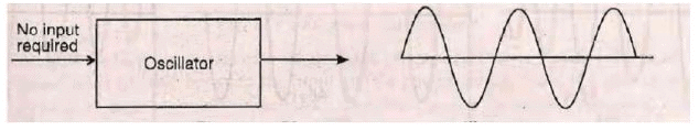
- Oscillator :is a circuit that changes dc energy from the power supply into ac energy.
- An amplifier provided with a positive feedbackbecomes an oscillator and it produces an output signal even thought there is no external input signal as shown.
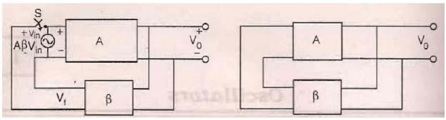
A voltage sourceVin drives the input terminals of an amplifier. The amplifier output voltage is AVin and it drives the feedback network producing a feedback voltage Vf = A Vin . If the circuit of the amplifier and the feedback network provide correct phase shift, then this feedback voltage Vf will be in phase with signal Vin that drives the input terminals of the amplifier. Now, if switch is closed and simultaneously the voltage source Vin is removed, the feedback voltage Vf will drive the input terminals of the amplifier.
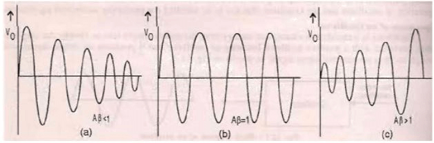
-If A is less than 1, A Vin will be less than Vin ,the signal feedback is not sufficient to drive the amplifier and the feedback circuits and the output will die out. -If A >1, the output signal builds up resulting in oscillations with growing magnitude . -If A =1, A Vin =Vin and the output voltage is a sine wave whose amplitude remains constant.
From the basic feedback equation
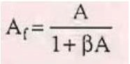
- with A = -1and the term in the denominator becomes zero , then Af becomes infinite.
- Therefore, an infinitesimal signal (noise voltage) can produce an output signal even without an input signal and the circuit acts as an oscillator.
- The oscillations will not be sustained if, the magnitude of the product of the transfer gain amplifier and the magnitude of feedback factor of the feedback network is less than unity.
- The condition IA I = 1is called the Barkhausen criterion.
- It implies that when IA I =1, there exists an output voltage even in absence of any externally applied signal.
If IA I = 1precisely ,then after sometimes it is found that the A will either become lower or higher than unity .this due to change in the characteristics of active devices with voltage , temperature or ….
- Therefore, A is kept slightly larger than unity so that any variation in circuit parameters may not cause A to become less than unity otherwise the oscillation will stop.
So, we can summarize the requirements of an oscillator circuit as:
- 1. Initially, the loop gain must be greater than unity at oscillator frequency.
- 2. After the desired output level is reached, A must decreaseto 1
- 3. At oscillator frequency, net phase shift around the loop must be zero or integer multiple of 360°so that the feedback signal is in phase with the starting infinitesimal voltage.
Phase Shift Oscillator:
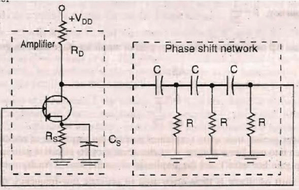
A phase shift oscillatorconsists of a single stage of amplifier that amplifies the input signal and produces a phase shiftof 180°the input and its output signal.
- If a part of this output is taken and fed back to input, it results in negative feedbackca using the output voltage to decrease.
- But we require positive feedbackwhich means that the voltage
- signal feedback should be in phase with the input signal.
- The output of the amplifier should taken through a phase-shift networkto provide it an additional phase shift of 180°.
- Amplifier provides a phase shift of 180°and the phase-shift network also gives a 180°and therefore, a total phase-shift of 360°(which is equivalent to 0°) results. The RC network provides the required phase shift by using three RC
- Each having some value of R and C. these values are selected so as to produce 60°phase shift per section,resulting in total of 180°phase shift as desired .
- But in actual practice each RC-section does not provide the same phase shift because each section loads the previous one but the over all phase shift is 180°which is the requirement .
- The O/P of the phase shift network is connected to the I/P of the amplifier
- The frequency at which phase shift is 180°is :
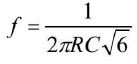
This the frequency of oscillation
At this frequency =1/29
- For loop gain A to be greater than unity,gain of amplifier stage
- must be greaterthan 29 ; A >1
=>A>1/
=>A>29.
Wein Bridge Oscillator
The principle
This type of oscillation uses two stages of amplifiers each providing a phase shift of 180.
The O/P of second stage is fed back to the I/P through a feed back network without producing any further phase shift .
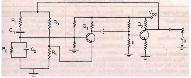
WBO
- The wein bridge oscillator uses two stages to provide 180 phase shift per stageand a bridge network to control the frequency of oscillation
- The bridge network consists of two parallel branches, each of which acts as a voltage divider for the feed-back voltage.
- One branch contains R3 and R4, and the other contains R1, C1, and R2, C2
- The feedback voltage developed across R4 of R3 R4 branch is applied to emitter of Q1, and the portion of voltage across R2 C2 of R1 C1,-R2 C2 branch is applied to base of Q1,.
- The polarity of feedback applied to the baseis such that it is regenerative (positive), and the feedback applied to emittertends to be degenerative (negative).
- For the circuit to oscillate, the positivefeedback must be greaterthan the negative feedback. At the frequency of oscillation, fo, the voltage across R4is less than that across R2C2
- So, the circuit oscillates.
As the frequency increases, reactance of the capacitor C2decreases.
- Since C2shunts R2, the impedance of R2C2combination decreases, reducingthe positivefeedback applied to the base below the level of negative feedback applied to emitter.
- If the frequency tends to decrease, the reactance of C1increases causing more of the feedback voltage to be dropped across C1.
- This results in a corresponding decrease in positive feedbackdeveloped across R2C2. Hence, the positive feedback again becomes less than the negative feedback, preventing the circuit from oscillating.
The frequency of oscillation of the oscillator can be varied by varying C1, and C2 simultaneously.
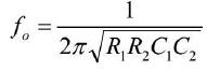
- The frequency of oscillation of the oscillator is given by :
RC oscillator using op-amp
Phase shift oscillator which consists of an op-amp as the amplifying stage and three RC cascade networks as the feedback circuit is shown.
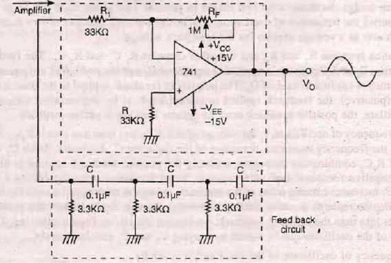
RC oscillator using op-amp
- The feedback circuit provides feedback voltage from the output back to the input of the amplifier.
- The output of op-amp is shifted by 180°at the output. An additional 180°phase shift required for oscillation is provided by the cascaded RC networks.
- Thus the total phase shift around the loop is 360°.
- At some specific frequency when the phase shift of the cascaded RC networks is exactly 180°and the gain of the amplifier is sufficiently large, the circuit will oscillate at that frequency.
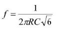
This frequency called the frequency of oscillation fo and is
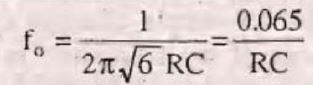
The circuit produces a sinusoidal waveform of frequency foif the gain is 29 and the total phase shift is exactly 360°.
- For a desired frequency of oscillation, choose a capacitor C, and then calculate the value of R.
Hartley Oscillator :-
This oscillator has two parts of coil .The first part is in the input circuit of cthe transistor and the other part is in the output circuit .The first part is used to supply ac voltage and the other part develops the positive feedback signal to sustain oscillation. The capacitor C1and the tapped coil L1 determine the frequency of the oscillator . The two sections of tapped coil are L1a and L1b. L1ais in the base circuit and L1bis in the collector circuit of the transistor.
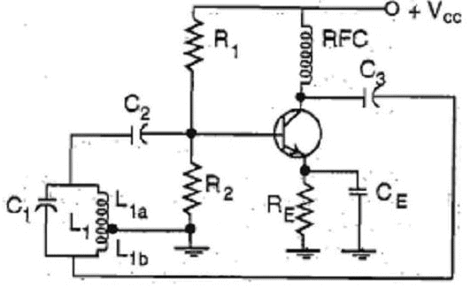
When VCC is applied ,the collector current begins to flow. The drop in collector voltage is coupled through C3 and developed across L1b.
- This act as initial excitation for the tank causing a circulating current to flow in the tank.
- This circulating current induced voltage across L1awhich drives the base of the transistor.
- The amplified signal at the collector is coupled back to the tank circuit by C3and developed across L1b.
- The feedback voltage L1bis in phase with the input voltage across L1aand hence results in oscillations.
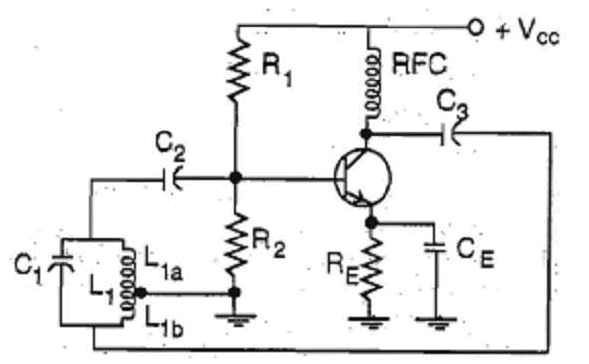
The F.B voltage is in phase with the input voltage as180°phase shift occurs between signal at base and collector, and another 180°is being provided by the fact that the two ends of coil L1 are of opposite polarity.
- The capacitor C3 blocks the dc components of collector circuit but couples ac signal.
- The dc components flows to Vcc supply through r-f choke which also prevents ac components from following this path as RFC acts as a dc short and ac open.
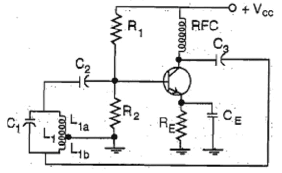
The value of L,C determine the frequency of oscillation:
Remark
Radio frequency inductor
- (RF), inductors have radio frequencies , particularly high frequencies At higher resistance and other losses. In addition to causing power loss, in of the circuit, broadening Q factor this can reduce the resonant circuits .RF inductors, are specialized construction techniques bandwidth the which used to minimize these losses.
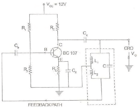
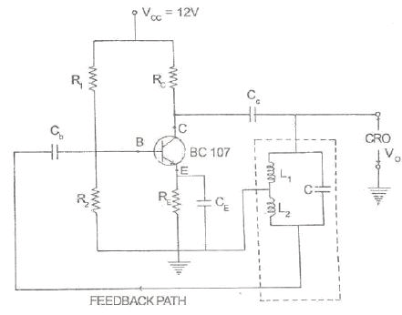
Hartley Oscillator:-Description:
- The Hartley oscillator is designed for generation of sinusoidal oscillations in the R.F range (20 KHz -30 MHz).
- It is very popular and used in radio receivers as a local oscillator.
H.O
- The circuit diagram consists of an CE amplifier configuration.
- R1and R2form a voltage divider.
- The coupling capacitor Cc blocks dc and provides an ac path from the collector to the tank circuit.
- The feedback network (L1, L2and C) determines the frequency oscillation of the oscillator.
H.O
- When the collector supply voltage Vcc is switched on, due to some transient disturbances in the circuit the collector current starts rising and charges the capacitor C.
- It discharges through coils L1and L2, setting up oscillations in the tank circuit.
- The oscillatory current in the tank circuit produces an a.c voltage which is applied to the base emitter junction of the transistor and appears in the amplified form in the collector circuit.
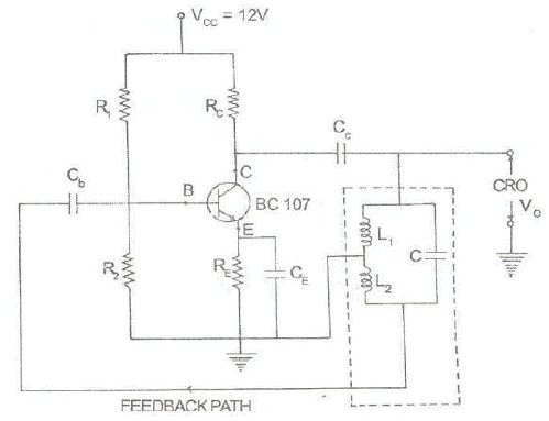
- The phase difference between the voltages across L1and that across L2is always 180°because the centre of the two is grounded.
- A further phase of 180°is introduced between the input and output the voltages by transistor itself.
- Thus the total phase shiftbecomes 360°(or zero), thereby making the feedback positive or regenerative which is essential for oscillations. So continuous oscillations are obtained.
The Crystal Oscillation
- A crystal oscillator is a tuned circuit using a crystal as a resonant circuit. Oscillator provides great frequency stability.
- They use crystal slices, usually made of quartz. The crystal materials exhibits the piezoelectric effect. When the voltage is applied across a piezoelectric (usually quartz),
- The crystal oscillates in a stable and accurate manner. The frequency of oscillation is determined by the crystal dimensions.
- Commercial quartz crystals are ready available with frequencies from a few kilohertz to a few hundred megahertz.
- If mechanical pressure is put on such a crystal, electrical charges appear across its faces, and an ac voltage can be generated.
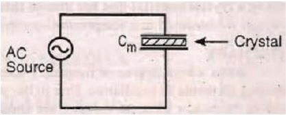
- If a crystal is excited by an ac voltage the crystal generates a significant ac voltage. For use in electronic circuit , the crystal is cut and mounted between two metal plates.
Consider that an acsource is connected across it . when the mounted crystal is not vibrating ,it is equivalent to a capacitance Cm because it has two metal plates separated by a dielectric
- When ac voltage is applied to the crystal ,it starts vibrating .
the natural resonant frequency depends on the type of material, how it is cut and its physical dimensions.
- The natural frequency of a crystal is inversely proportional to its thickness.
- This property of crystals make them highly useful in the oscillator circuits.
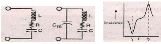
The crystal has two resonant frequencies. The crystal behaves as a parallel resonant circuit at a frequency at which the series LCR branch has an inductive reactance which equal to the capacitive reactance of Cm.
- This parallel combinationoffers maximum impedance . The series resonant frequency fsof crystal is the resonant frequency of LCR branch. At this frequency, the impedance of LCR branch is minimum.
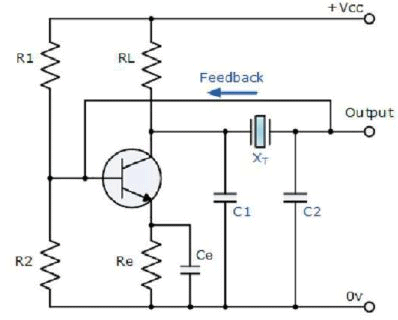
Colpitts Crystal Oscillator
- This figure shows a Colpitts crystal oscillator .
- The input signal to the base of the transistor is inverted at the transistors output.
- The output signal at the collector is then taken through a 180o phase shifting network which includes the crystal operating in a series resonant mode.
FAQs on Feedback and Oscillator Circuit (Part - 3) - Electrical Engineering (EE)
| 1. What is the purpose of feedback in an oscillator circuit? |  |
| 2. How does positive feedback contribute to oscillations in a circuit? | |
| 3. What is the significance of the frequency-determining components in an oscillator circuit? | |
| 4. How does an oscillator circuit maintain a constant amplitude of oscillations? | |
| 5. What are some common types of oscillator circuits? | |


Feedback and Oscillator Circuit (Part - 3) - Electrical Engineering (EE)
,ppt
,study material
,mock tests for examination
,Semester Notes
,Extra Questions
,Previous Year Questions with Solutions
,Important questions
,Free
,video lectures
,MCQs
,Summary
,past year papers
,Feedback and Oscillator Circuit (Part - 3) - Electrical Engineering (EE)
,Sample Paper
,Exam
,practice quizzes
,Objective type Questions
,Viva Questions
,Feedback and Oscillator Circuit (Part - 3) - Electrical Engineering (EE)
,shortcuts and tricks
;


Feedback and Oscillator Circuit (Part - 3) Free PDF Download
Importance of Feedback and Oscillator Circuit (Part - 3)
Feedback and Oscillator Circuit (Part - 3) Notes
Feedback and Oscillator Circuit (Part - 3) Electrical Engineering (EE) Questions
Study Feedback and Oscillator Circuit (Part - 3) on the App
|
© EduRev
|
Education Revolution
|


|


within 7 days!