Force on Current Carrying Conductor | Physics for JEE Main & Advanced PDF Download
3. FIELD DUE TO A STRAIGHT CURRENT CARRYING WIRE
3.1 WHEN THE WIRE IS OF FINITE LENGTH
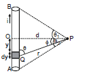
Consider a straight wire segment carrying a current i and there is a point P at which magnetic field to be calculated as shown in the figure. This wire segment makes angle θ1 and θ2 at that point with normal OP. Consider an element of length dy at a distance y from O and distance of this element from point P is r and line joining P to Q makes an angle q with the direction of current as shown in figure. Using Biot-Savart Law magnetic field at point P due to small current element is given by
As every element of the wire contributes to in the same direction, we have

....(i)
From the triangle OPQ as shown in diagram, we have
y = d tan 
or dy = d sec2 d
d
and is same triangle,
r = d sec  and q = (90º -
  ), where
  is angle between line OP and PQ
Now equation (i) can be written in this form
or ...(3)
Note : θ1 & θ2 must be taken with sign
For the case shown in figure
B at A =
Direction of  : The direction of magnetic field is determined by the cross product of the vector
 with
. Therefore, at point P, the direction of the magnetic field due to the whole conductor will be perpendicular to the plane of paper and going into the plane.
Right-hand Thumb Rule : The direction of B at a point P due to a long, straight wire can be found by the right-hand thumb rule. The direction of magnetic field is perpendicular to the plane containing wire and perpendicular from the point. The orientation of magnetic field is given by the direction of curl fingers if we stretch thumb along the wire in the direction of current. Refer figure.
Conventionally, the direction of the field perpendicular to the plane of the paper is represented by if into the page and by
if out of the page.
Now consider some special cases involving the application of equation (3)
Case 1 : When the point P is on the perpendicular bisector
In this case angle θ1 = θ2, using result of equation (3), the magnetic field is
where 
Case - 2
(i) If the wire is infinitely long then the magnetic field at `P' (as shown in the figure) is given by (using q1 = q2 = 90° and the formula `B' due to straight wire)
B = ⇒ B µ

The direction of at various is as shown in the figure. The magnetic lines of force will be concentric circles around the wire (as shown earlier)
(ii) If the wire is infinitely long but `P' is as shown in the figure. The direction of at various points is as shown in the figure. At `P'
B =
Case III : When the point lies along the length of wire (but not on it)
If the point P is along the length of the wire (but not one it), then as and
will either be parallel or antiparallel, i.e., q = 0 or p, so
and hence using equation (1)
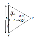
Ex-1 Calculate the magnetic field induction at a point distance, metre from a straight wire of length `a' metre carrying a current of i amp. The point is on the perpendicular bisector of the wire.
Sol. B = [sinq1 + sinq2]
= 10-7

=
Perpendicular to the plane of figure (inward).
Ex.2 Find resultant magnetic field at `C' in the figure shown.

Sol. It is clear that `B' at `C' due all the wires is directed Ä. Also B at `C due PQ and SR is same. Also due to QR and PS is same
Therefore, Bres = 2(BPQ + BSP)
BPQ = (sin 60° + sin 60°)
BSP = (sin 30° + sin 30°)
⇒ Bres = =
Ex.3 Figure shows a square loop made from a uniform wire. Find the magnetic field at the centre of the square if a battery is connected between the points A and C.
Sol. The current will be equally divided at A. The fields at the centre due to the currents in the wires AB and DC will be equal in magnitude and opposite in direction. The resultant of these two fields will be zero. Similarly, the resultant of the fields due to the wires AD and BC will be zero. Hence, the net field at the centre will be zero.
Ex.4 In the figure shown there are two parallel long wires (placed in the plane of paper) are carrying currents 2 I and I consider points A, C, D on the line perpendicular to both the wires and also in the plane of the paper. The distances are mentioned.

Find (i) at A, C, D
(ii) position of point on line A C D where is zero.
Sol. (i) Let us call due to (1) and (2) as
and
respectively. Then
at A : is
and
is
B1 = and B2 =
Therefore, Bres = B1 - B2 =
Ans.
at C: is
and
also
Therefore, Bres = B1 + B2 =
+
=
=
Ans.

Therefore, Bres = 0 Ans.
(ii) It is clear from the above solution that B = 0 at point `D'.
|
268 videos|732 docs|171 tests
|
FAQs on Force on Current Carrying Conductor - Physics for JEE Main & Advanced
| 1. What is the force on a current-carrying conductor? |  |
| 2. How is the direction of the force determined on a current-carrying conductor? |  |
| 3. Does the force on a current-carrying conductor depend on the magnitude of the current? |  |
| 4. How does the length of the conductor affect the force on it? |  |
| 5. Can the force on a current-carrying conductor be used to create motion? |  |


