Freewheel Diode | Power Electronics - Electrical Engineering (EE) PDF Download
Introduction
A Flyback diode is also called as freewheeling diode. It is also called by many other names like snubber diode, suppressor diode, catch diode or clamp diode, commutating diode. Here catch diode is used to eliminate flyback, when the abrupt voltage spike is witnessed across the inductive load when the supply current abruptly reduced. It helps the circuit from damaging. It will get prevented from buying new circuit. Freewheeling diode is simplified form where voltage source is connected to an inductor with a switch.
Design of the Freewheeling Diode
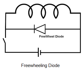
In the below diagram a freewheeling diode is placed across the inductor. An ideal flyback diode will have a very large peak forward current; capacity which helps in handling the voltage transients from burning out the diode, inductor’s power supply is suited for reverse breakdown voltage and low forward voltage drop. Voltage surges can be 10times to the voltage of power source which depends on the equipment involved and the application. It is understood that not to underestimate the energy which contain within an energized inductor.
Flywheel diode may cause delay drop put of contacts when the power is removed and DC coil relay is used. This is due to the continuous circulation of current in the diode and the relay coil. The opening of contacts is very important because a low value resistor is placed in series with the diode, which helps in dissipating the coil energy faster.
In flywheel application Schottky diodes are used for switching power converters, because they will have lowest forward drop i.e. 0.2V. These are also responding quickly in reverse bias in the case of the inductor is being re energized. While transferring the energy from inductor to a capacitor it dissipates less energy.
Freewheeling Diode Working
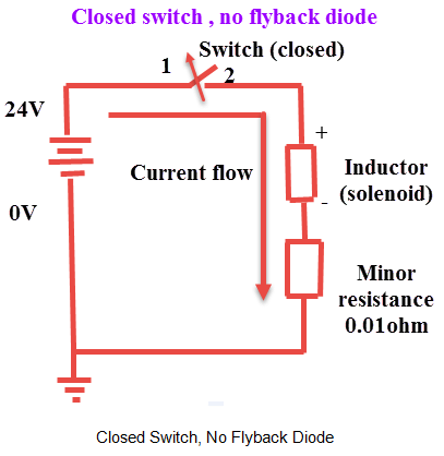
The working principle of freewheeling diode will be simple and will be explained with three circuits. That will make clear understanding how it actually works. In the steady-state, the switch will be closed for a long time so, that the inductor gets fully energized and behaves as though it is a short
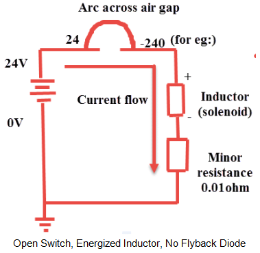
 Now the current will flow down from the positive terminal to the negative terminal of the voltage source, through the inductor. If the switch is opened, the inductor will resist the sudden drop of current. If dI/dt is large then voltage is large by using its stored magnetic field energy and will create its own voltage.
 An extremely large positive potential is created where there was once negative potential, and a negative potential is created where there was once positive potential. The switch will remains at the voltage of the power supply, but it has remained in contact with the inductor and will pull down negative voltage. Since the switch is being open therefore no connection is physically made to allow current to continue to flow, arc across the air gap is caused due to the large potential difference of the open switch.
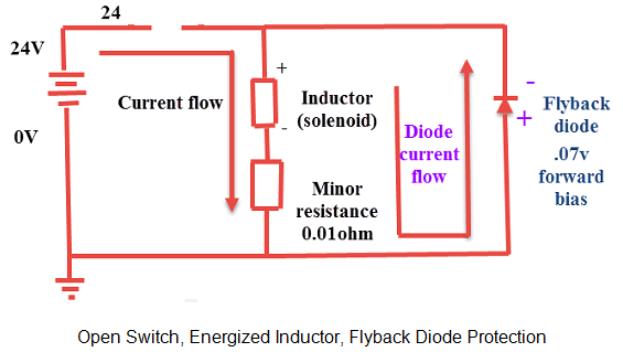
Now this is solved by using Flyback diode. The starvation-arc problem by allowing until the energy is dissipated through losses in the wire by the inductor to draw current from it in a continuous loop, the diode and the resistor. The diode will be reversed biased when the switch is closed against the power supply and which doesn’t exist in the circuit for practical purposes. However, the diode becomes forward-biased when the switch is opened, in relative to the inductor, and allows conducting current in a circular loop from the positive potential at the bottom of the inductor to the negative potential at the top. The voltage across the inductor will be a function of the forward voltage drop of the Flyback diode. Total time for dissipation may vary, but it will last for a few milliseconds.
Freewheel diode or Flyback diodes are basically connected across inductive coils to prevent from voltage spikes in case of power getting turned off to the devices. There will sharp voltage spike when power to inductive load, i.e. coils and other inductors are turned off. Then, according to Lenz law the direction of this voltage will be opposite to the applied voltage. The coil of the relay gets magnetically charged when current starts to flow and stores the energy in the magnetic field around the coil.
The current in the coil tends to decrease if there is a power supply interruption, this effect will lead to a surge in the voltage. The induced voltage will jump across the contacts of the relays which are connected to the coils. The life of the contacts will be affected when sparks and arcing is produced.
The transistors which can be driving the relay coils will get damaged the electronic components with the voltage spike. The voltage spike will be in the reverse direction when the freewheeling diodes are connected in reverse bias to the supply voltage. When this happens then short circuit takes place through the diode. The voltage spike is thus short-circuited across the coil. This will protect the connected circuits.
From the equation V=Ldi/dt an inductive device generates the voltage. The value of di/dt will be large, when the current suddenly drops to zero, which results in “inductive kick” voltage. This results in damaging the other components. The Flyback diode will provide a path for inductive current to flow. Now it can be said that the current through the diode/ inductor combination at the time of turnoff will be equal to the current flowing just before the turn off.
The decay exponential I = imax(1-exp(-Lt/R)
Imax = initial current
t = turn off
L = inductance
R = equivalent series resistance of the circuit
The Main Principle of Flyback Diode
When the transistor is ON, it will be in reverse biased and won’t exist in a circuit. When the transistors OFF, Flyback diode will be forward biased. The Flyback diode will make the inductor to draw current from itself in a form of loop until the whole energy is dissipated in wires and diode. The Flyback diode makes inductor to draw current from itself in a loop until the energy is dissipated in diode and wires.
When the current flow to an AC induction motor is suddenly interrupted, then the inductor tries to maintain increasing the voltage and the current by reversing polarity. In the absence of “freewheeling diode” the voltage may go very high and can damage the switching device IGBT, Thyristor, etc. By this, the reverse current is allowed to flow through the diode and dissipate.
When a single switch is used with a switched iron or ferrite cored transformer, then the freewheeling diode will slow down the rate of current change and will not transfer power to the secondary side and when the inductor is switched back by the switching device and most probably it will saturate the core to pass a heavy current. In switched transformer, it is better not to use a freewheeling diode with a motor to break it and will waste power in the diode itself when needs a good heat sink.
Freewheeling Diode Applications
Inductive loads are switched off by semiconductor devices
- Relay drivers
- H-bridge motor drivers
- Full wave rectifier
|
5 videos|73 docs|46 tests
|


