HC Verma Questions and Solutions: Chapter 32: Electric Current in Conductors- 3 | HC Verma Solutions - JEE PDF Download
Q.43. Consider the circuit shown in the figure. Find (a) the current in the circuit (b) the potential drop across the 5 Ω resistor (c) the potential drop across the 10 Ω resistor (d) Answer the parts (a), (b) and (c) with reference to the figure.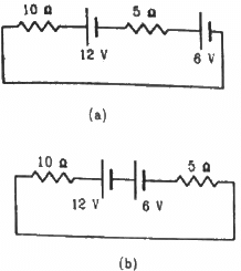
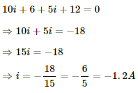
(a) Applying KVL in the above loop, we get:-
The negative sign indicates that current is flowing in the direction opposite to our assumed direction.
(b) Potential drop across the 5 Ω resistor= 5i = 5×(-1.2 ) = -6 V
(c) Potential drop across the 10 Ω resistor = 10i = (-1.2) × 10 = 12 V
(d) Applying KVL in the above loop, we get:-
Potential drop across the 5Ω register = -6 V
Potential drop across the 10Ω register = -12 V
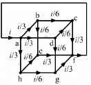
Q.44. Twelve wires, each of equal resistance r, are joined to form a cube, as shown in the figure. Find the equivalent resistance between the diagonally-opposite points a and f.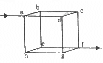
Let V be the potential difference between the points a and f. Let current i enter a and leave from f. The distribution of current in various branches is shown in figure.
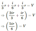
To calculate the potential difference between a and f, consider the path abcf and apply Kirchofff's Law:-
The effective resistance between a and f,
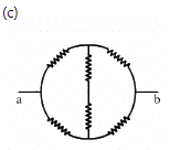
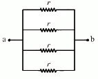
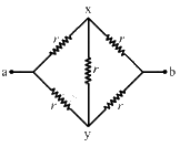
Q.45. Find the equivalent resistances of the networks shown in the figure between the points a and b.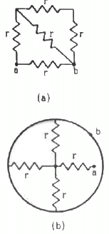
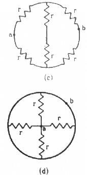
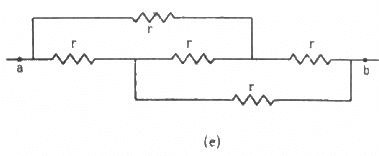
(a) The circuit can be simplified stepwise, as shown below.
The effective resistance between the points a and b,
(b) The circuit can be simplified, as shown below.
The effective resistance between the points a and b,
From the figure, it can be seen that axbya is a balanced Wheatstone bridge. The resistors in branch xy will, thus, become ineffective. The circuit can be simplified as under
The effective resistance between the points a and b,
(d) The circuit can be simplified as shown below.
The effective resistance between the points a and b,
(e) The circuit can be redrawn as shown below.
Now, we can see that the circuit is a balanced Wheatstone bridge. So, the branch xy will become ineffective. Thus, the simplified circuit will become as shown below.
The effective resistance between the points a and b,
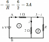
Q.46. An infinite ladder is constructed with 1 Ω and 2 Ω resistors, as shown in the figure. (a) Find the effective resistance between the points A and B. (b) Find the current that passes through the 2 Ω resistor nearest to the battery.
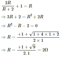
(a) Let the effective resistance of the combination be R. The circuit can be redrawn as shown below.
From the figure,
(b) Total current sent by the battery
Applying Kirchoff's Law in loop 1, we get:-
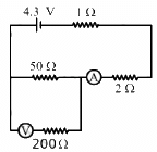
Q.47. The emf ε and the internal resistance r of the battery, shown in the figure, are 4.3 V and 1.0 Ω respectively. The external resistance R is 50 Ω. The resistances of the ammeter and voltmeter are 2.0 Ω and 200 Ω respectively. (a) Find the readings of the two meters. (b) The switch is thrown to the other side. What will be the readings of the two meters now?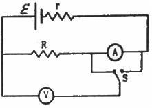
(a)
The 50 Ω and 200 Ω resistances are in parallel. Their equivalent resistance,
This equivalent resistance and the 2 Ω and 1 Ω resistances are connected in series. The effective resistance of the circuit,
In this case, the ammeter will read the total current of the circuit. The current through the ammeter,
This current will be distributed in the inverse ratio of resistance between the resistances 50 Ω and 200 Ω. The current through the voltmeter,
Reading of the voltmeter = 0.02 × 200 = 4 V
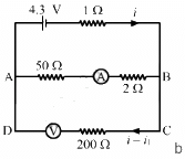
(b)
The two branches AB and CD are in parallel. Their equivalent resistance,
This equivalent resistance is in series with the 1 Ω resistance. The effective resistance of the circuit,
The total current through the circuit,
In this case, the ammeter will read the current flowing through the 50 Ω resistance, which is i1, as shown. The currents in the two parallel branches will distribute in the inverse ratio of the resistances.
The current through the voltmeter = i - i1 = 0.02 A
The reading of the voltmeter = 0.02 × 200 = 4 V
Q.48. A voltmeter of resistance 400 Ω is used to measure the potential difference across the 100 Ω resistor in the circuit shown in the figure. (a) What will be the reading of the voltmeter? (b) What was the potential difference across 100 Ω before the voltmeter was connected?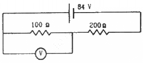
(a) The effective resistance of the circuit,
The current through the circuit,
Since 100 Ω resistor and 400 Ω resistor are connected in parallel, the potential difference will be same across their ends. Let the current through 100 Ω resistor be i1 ; then, the current through 400 Ω resistor will be i - i1.
The reading of the voltmeter = 100 × 0.24 = 24 V
(b) Before the voltmeter is connected, the two resistors 100 Ω resistor and 200 Ω resistor are in series.
The effective resistance of the circuit,
The current through the circuit,
∴ Voltage across the 100 Ω resistor = (0.28 × 100) = 28 V
Q.49. The voltmeter shown in the figure reads 18 V across the 50 Ω resistor. Find the resistance of the voltmeter.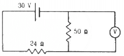
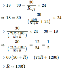
Let R be the resistance of the voltmeter. For the given circuit, 50 Ω and R are in parallel. The equivalent resistance of these two resistors,
This equivalent resistance is now in series with the 24 Ω resistor. The effective resistance of the circuit,
Current through the circuit,
Voltage across the 24 Ω resistor, V1 =
Voltage across the 50 Ω resistor, V2 =
It is given that V2 = 18 V
Q.50. A voltmeter consists of a 25 Ω coil connected in series with a 575 Ω resistor. The coil takes 10 mA for full-scale deflection. What maximum potential difference can be measured by this voltmeter?
It is given that for maximum current, i = 10 mA, the potential drop across the voltmeter will be maximum.
The effective resistance of the circuit,
The maximum value of potential difference measured,
V = Reff × i
= 600 × 10 × 10−3
= 6 V
Q.51. An ammeter is to be constructed that can read currents up to 2.0 A. If the coil has resistance of 25 Ω and takes 1 mA for full-scale deflection, what should be the resistance of the shunt used?
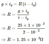
Let R be the resistance of the shunt used.
Coil resistance, g = 25 Ω
Current through the coil, ig = 1 mA
Total current i through the circuit in which the ammeter is connected = 2 A
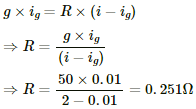
Since R and g are connected in parallel,
Q.52. A voltmeter coil has resistance 50.0 Ω and a resistor of 1.15 kΩ is connected in series. It can read potential differences up to 12 volts. If this same coil is used to construct an ammeter that can measure currents up to 2.0 A, what should be the resistance of the shunt used?
The effective resistance for the voltmeter,
Reff = (1150 + 50) Ω = 1200 Ω
The maximum current ig through the coil for maximum deflection of 12 V,
Let R be the resistance of the shunt used for ammeter.
Resistance of the coil, g = 50 Ω
Maximum deflection current, i, through the ammeter = 2 A
Since R and g are connected in parallel,
Q.53. The potentiometer wire AB shown in the figure is 40 cm long. Where should the free end of the galvanometer be connected on AB, so that the galvanometer may show zero deflection?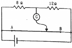
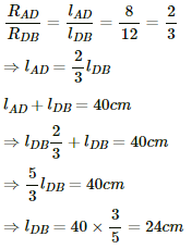
Let D be the null-point of the potentiometer. Since the bridge is balanced at this point,
According to the principle of a potentiometer,
Hence, the null-point is obtained 24 cm from B.
Q.54. The potentiometer wire AB shown in the figure is 50 cm long. When AD = 30 cm, no deflection occurs in the galvanometer. Find R.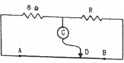
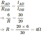
It is given that at point D, there is no deflection in the galvanometer, i.e. the bridge is balanced
According to the principle of a potentiometer,
Q.55. A 6-volt battery of negligible internal resistance is connected across a uniform wire AB of length 100 cm. The positive terminal of another battery of emf 4 V and internal resistance 1 Ω is joined to the point A, as shown in the figure. Take the potential at B to be zero. (a) What are the potentials at the points A and C? (b) At which point D of the wire AB, the potential is equal to the potential at C? (c) If the points C and D are connected by a wire, what will be the current through it? (d) If the 4 V battery is replaced by a 7.5 V battery, what would be the answers of parts (a) and (b)?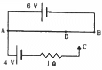
(a) Potential difference across AB = Potential at A - Potential at B
Potential at B = 0 V
⇒ Potential at point A = Potential difference across AB = 6 V
⇒ Potential difference across AC = Potential at A - Potential at B
⇒ 4 = 6 - Potential at C
⇒ Potential at C = 2 V
(b) Given:-
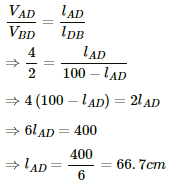
Potential across AD = Potential across AC = 4 V
⇒ Potential across DB = 2 V
(c) When the points C and D are connected by a wire, current flowing through the wire will be zero because the points are at the same potential.
(d) Potential difference across AC = Potential at A - Potential at C
⇒ 7.5 = 6 - Potential at C
⇒ Potential at C = −1.5 V
Since the potential at C is negative now, this point will go beyond point B, which is at 0 V. Hence, no such point D will exist between the points A and B.
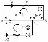
Q.56. Consider the potentiometer circuit as arranged in the figure. The potentiometer wire is 600 cm long. (a) At what distance from the point A should the jockey touch the wire to get zero deflection in the galvanometer? (b) If the jockey touches the wire at a distance of 560 cm from A, what will be the current in the galvanometer?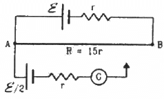
Let X be the null point on the wire at a distance x cm from point A, as shown.
Given:-
Total resistance of the wire AB = 15r
Resistance per unit cm = 15r/600
Resistance of x cm of the wire = 15rx/600
Resistance of (600 - x ) cm of the wire =
(a) Applying KVL in loop 1, we get:-
For zero deflection in the galvanometer, i2 = 0. From equation (2),
Substituting the values of i1 and i2 in equation (1), we get:-
x = 320 cm
(b) Putting x = 560 cm and solving equations (1) and (2), we get:-
Q.57. Find the charge on the capacitor shown in the figure.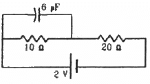
In steady state, the capacitor is fully charged and then, it offers infinite resistance to the direct current flow. So, no current can flow through the capacitor in steady state.
The effective resistance of the circuit,
Reff = 10 + 20 = 30 Ω
The current i through the circuit,
Voltage drop across the 10 Ω resistor,
V = i × r
Since the potential drops across the capacitor and the 10 Ω resistor are the same, the charge stored on the capacitor,
Q = CV
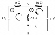
Q.58. (a) Find the current in the 20 Ω resistor shown in the figure. (b) If a capacitor of capacitance 4 μF is joined between the points A and B, what would be the electrostatic energy stored in it in steady state?
(a) Applying Kirchoff's voltage law in loop 1, we get:
In the circuit ABEDA,
10i1 + 20 (i1 + i2) − 5 = 0
⇒ 30i1 + 20i2 = 5 ............(1)
Applying Kirchoff's voltage law in loop 2, we get:-
20 (i1 + i2) − 5 + 10i2 = 0
⇒ 20i1 + 30i2 = 5 ...........(2)
Multiplying equation (1) by 20 and (2) by 30 and subtracting (2) from (1), we get:-
i2 = 0.1 A
and i1 = 0.1 A
∴ Current through the 20 Ω resistor = i1 + i2 = 0.1 + 0.1 = 0.2 A
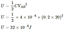
(b) Potential drop across across AB is,
Electrostatic energy stored in the capacitor is given by,
Q.59. Find the charges on the four capacitors of capacitances 1 μF, 2 μF, 3 μF and 4 μF shown in the figure.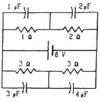
When the capacitors are fully charged, they attain steady state and no current flows through them. Then, equivalent resistance of the circuit,
Current through the circuit,
Current i is divided in the inverse ratio of the resistance in each branch. One branch has resistance of 3 Ω and the other branch has resistance of 6 Ω.
Current i' through the 3 Ω branch,
Current i'' through the 6 Ω branch,
Voltage across the 1 Ω resistor = 2 A × 1 Ω = 2 V
Charge on the 1 μF capacitor = 2 × 1 μF = 2 μC
Voltage across the 2 Ω resistor = 2 Ω × 2 A = 4 V
Charge on the 2 μF capacitor = 4V × 2 μF = 8 μC
Voltage across each 3 Ω resistor = 3 Ω × 1 A = 3 V
Charge on the 4 μF capacitor = 3 × 4 μC = 12 μC
Charge on the 3 μF capacitor = 3 × 3 μC = 9 μC
Q.60. Find the potential difference between the points A and B and between the points B and C of the figure in steady state.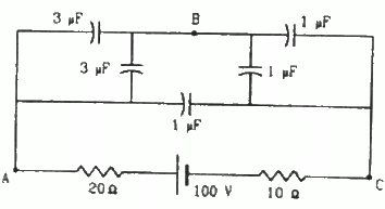
Equivalent capacitance of the circuit can be calculatesd as,
Ceq:-
V = 100 V
Total charge in the circuits is,
As the volatge across 1μf is 100 V, therfore charge stored on 1 μf capacitors = 100 μC
Charge flowing from A to B = (250 - 100) = 150 μC
Ceq between A and B is 6 μf.
Potential drop across AB,
Potential drop across BC = (100 - 25) = 75 V
Q.61. A capacitance C, a resistance R and an emf ε are connected in series at t = 0. What is the maximum value of (a) the potential difference across the resistor (b) the current in the circuit (c) the potential difference across the capacitor (d) the energy stored in the capacitor (e) the power delivered by the battery and (f) the power converted into heat?
(a) When the charge on the capacitor is zero, it acts as short circuit.
Thus, maximum value of potential difference across the resistor = ε (at t = 0)
(b) Maximum value of current in the circuit
(c) Maximum value of potential difference across the capacitor = ε .............(at t = ∞, when the capacitor is fully charged and acts as a open circuit)
(d) Maximum energy stored in the capacitor
(e) Maximum power delivered by the battery
(f) Maximum power converted to heat
Q.62. A parallel-plate capacitor with plate area 20 cm2 and plate separation 1.0 mm is connected to a battery. The resistance of the circuit is 10 kΩ. Find the time constant of the circuit.
Given:-
Area of the plates, A = 20 cm2 = 20 × 10−4 m2
Separation between the plates, d = 1 mm = 1 × 10⁻³ m,
Resistance of the circuit, R = 10 kΩ
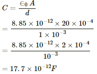
The capacitance of a parallel-plate capacitor,
Time constant = CR
= 17.7 × 10−12 × 10 × 103
= 17.7 × 10⁻⁸ s
= 0.177 × 10⁻⁶ s
= 0.18 μs
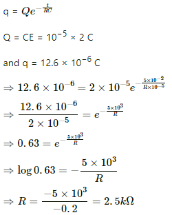
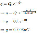
Q.63. A capacitor of capacitance 10 μF is connected to a battery of emf 2 V. It is found that it takes 50 ms for the charge of the capacitor to become 12.6 μC. Find the resistance of the circuit.
Given:-
Capacitance of the capacitor, C = 10 μF = 10−5 F
Emf of the battery, E= 2 V
Time taken to charge the capacitor completely, t = 50 ms
= 5 × 10⁻² s
The charge growth across a capacitor,
Q.64. A 20 μF capacitor is joined to a battery of emf 6.0 V through a resistance of 100 Ω. Find the charge on the capacitor 2.0 ms after the connections are made.
The growth of charge across a capacitor,
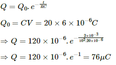
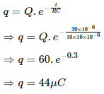
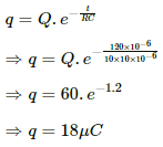
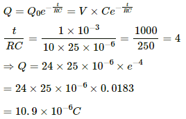
Q.65. The plates of a capacitor of capacitance 10 μF, charged to 60 μC, are joined together by a wire of resistance 10 Ω at t = 0. Find the charge on the capacitor in the circuit at (a) t = 0 (b) t = 30 μs (c) t = 120 μs and (d) t = 1.0 ms.
Given:-
Capacitance of the capacitor, C = 10 μF
Initial charge on capacitor, Q = 60 μC
Resistance of the circuit, R = 10 Ω
(a) Decay of charge on the capacitor,
(b) At t = 30 μs,
(c) At t = 120 μs,
(d) At t = 1 ms,
Q.66. A capacitor of capacitance 8.0 μF is connected to a battery of emf 6.0 V through a resistance of 24 Ω. Find the current in the circuit (a) just after the connections are made and (b) one time constant after the connections are made.
Given:-
Capacitance, C = 8 μF
Emf of the battery, V= 6 V
Resistance, R = 24
(a) Just after the connections are made, there will be no charge on the capacitor and, hence, it will act as a short circuit. Current through the circuit,
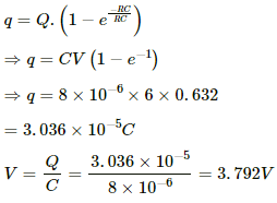
(b) The charge growth on the capacitor,
One time constant = RC = 8 × 24 = 192 × 10-6 s
For t = RC, we have:-
Applying KVL in the circuit, we get:-
E = V + iR
⇒ 6 = 3.792 + 24i
⇒ i = 0.09 A
Q.67. A parallel-plate capacitor of plate area 40 cm2 and separation between the plates 0.10 mm, is connected to a battery of emf 2.0 V through a 16 Ω resistor. Find the electric field in the capacitor 10 ns after the connections are made.
Given:-
Area of plates, A = 40 cm2 = 40 × 10−4 m2
Separation between the plates, d = 0.1 mm = 1 × 10⁻⁴ m
Resistance, R = 16 Ω
Emf of the battery,
V0 = 2V
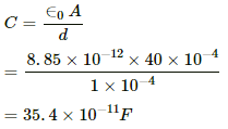
The capacitance C of a parallel plate capacitor,
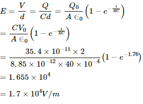
So, the electric field,
Q.68. A parallel-plate capacitor has plate area 20 cm2, plate separation 1.0 mm and a dielectric slab of dielectric constant 5.0 filling up the space between the plates. This capacitor is joined to a battery of emf 6.0 V through a 100 kΩ resistor. Find the energy of the capacitor 8.9 μs after the connections are made.
Given:-
Area of the plates, A = 20 cm2
Separation between the plates, d = 1 mm
Dielectric constant, k = 5
Emf of the battery, E = 6 V
Resistance of the circuit, R = 100 × 103 Ω
The capacitance of a parallel-plate capacitor,
After the connections are made, growth of charge through the capacitor,
= 335.6 × 10⁻¹² C
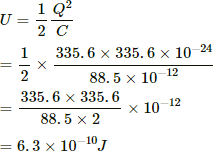
Thus, energy stored in the capacitor,
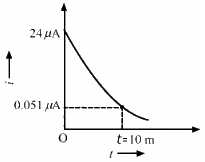
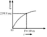
Q.69. A 100 μF capacitor is joined to a 24 V battery through a 1.0 MΩ resistor. Plot qualitative graphs (a) between current and time for the first 10 minutes and (b) between charge and time for the same period.
Time constant of the circuit,
τ = RC
= 1 × 106 × 100 × 10−6
= 100 s
The growth of charge through a capacitor,
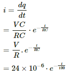
The current through the circuit,
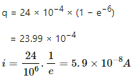
For t = 10 min = 600 s
(a) The plot between current and time for the first 10 minutes is shown below.
(b) The plot between charge and time for the first 10 minutes is shown below.
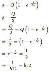
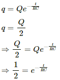
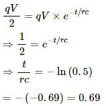
Q.70. How many time constants will elapse before the current in a charging RC circuit drops to half of its initial value? Answer the same question for a discharging RC circuit.
The growth of charge across a capacitor,
Let t = nRC
The decay of charge across a capacitor,
Let t = nRC
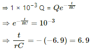
Q.71. How many time constants will elapse before the charge on a capacitors falls to 0.1% of its maximum value in a discharging RC circuit?
The decay of charge across a capacitor,
Here, q = 0.1 % and Q = 1 × 10⁻³ Q
Let t = nRC
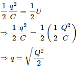
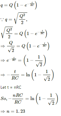
Q.72. How many time constants will elapse before the energy stored in the capacitor reaches half of its equilibrium value in a charging RC circuit?
The equilibrium value of energy in a capacitor,
where Q is the steady state charge.
Let q be the charge for which energy reaches half its equilibrium. Then,
The growth of charge in a capacitor,
Q.73. How many time constants will elapse before the power delivered by a battery drops to half of its maximum value in an RC circuit?
Power = CV2 = q × V
Now,
Q.74. A capacitor of capacitance C is connected to a battery of emf ε at t = 0 through a resistance R. Find the maximum rate at which energy is stored in the capacitor. When does the rate have this maximum value?
The rate of growth of charge for the capacitor,
Let E be the energy stored inside the capacitor. Then,
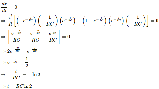
Let r be the rate of energy stored inside the capacitor. Then,
For r to be maximum,
Q.75. A capacitor of capacitance 12.0 μF is connected to a battery of emf 6.00 V and internal resistance 1.00 Ω through resistanceless leads. 12.0 μs after the connections are made, what will be (a) the current in the circuit (b) the power delivered by the battery (c) the power dissipated in heat and (d) the rate at which the energy stored in the capacitor is increasing?
Given,
Capacitance of capacitor, C= 12.0 μF = 12 × 10−6 F
Emf of battery, V0 = 6.00 V
Internal resistance of battery, R = 1 Ω
Time interval, t = 12 μs
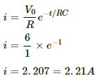
(a) Charging current in the circuit is given as,
i = i0e−t/RC
Current at, t = 12.0 μs
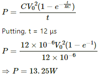
(b) During charging, charge on the capacitor at any time ''t'' is given as
Work done by battery in in time delivering this charge is,
W = QV0
Power deliver by the battery in time ''t'' is,
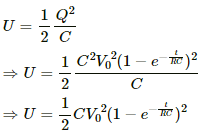
(c) Energy stroed in the capacitor at any instant of time is given as,
Rate at which the energy stored in the capacitor is,
So, the power dissipated in heat =
(d) Rate at which the energy stored in the capacitor is increasing
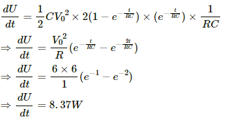
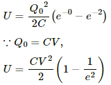
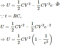
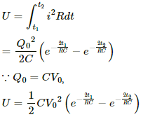
Q.76. A capacitance C charged to a potential difference V is discharged by connecting its plates through a resistance R. Find the heat dissipated in one time constant after the connections are made. Do this by calculating ∫ i2R dt and also by finding the decrease in the energy stored in the capacitor.
Let Q0 be the initial charge on the capacitor. Then,
Q0 = CV
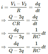
The charge on the capacitor at time t after the connections are made,
Heat dissipated during time t1 to t2,
Time constant = RC
Putting t1 = 0 and t2 = RC, we get:-Solution 2
Heat dissipated at any time = Energy stored at time 0 − Energy stored at time t
Q.77. By evaluating ∫i2Rdt, show that when a capacitor is charged by connecting it to a battery through a resistor, the energy dissipated as heat equals the energy stored in the capacitor.
The growth of charge on the capacitor at time t ,
Heat dissipated during time t1 to t2,
The potential difference across a capacitor at any time t,
The energy stored in the capacitor at any time t,
∴ The energy stored in the capacitor from t1 to t2,
Q.78. A parallel-plate capacitor is filled with a dielectric material of resistivity ρ and dielectric constant K. The capacitor is charged and disconnected from the charging source. The capacitor is slowly discharged through the dielectric. Show that the time constant of the discharge is independent of all geometrical parameters like the plate area or separation between the plates. Find this time constant.
The capacitance of a parallel plate capacitor,
The resistance of dielectric material,
Time constant,
which is independent of the plate area or separation between the plates.
Q.79. Find the charge on each of the capacitors 0.20 ms after the switch S is closed in the figure.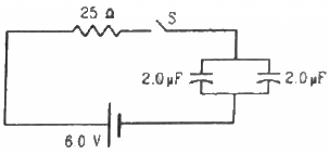
The equivalent capacitance of the circuit,
The growth of charge through the capacitor,
q = q0(1 − e−t/RC)
⇒ q = 24 × 10−6 (1 − e−2)
= 18.4 × 10⁻⁶ C
This is the total charge on both capacitors. As the capacitors are in parallel, the total charge will be shared between them. Also, both the capacitors are of same capacitance; so, they will share equal amount of charge.
∴ Charge on each capacitor
Q.80. The switch S shown in figure is kept closed for a long time and is then opened at t = 0. Find the current in the middle 10 Ω resistor at t = 1 ms.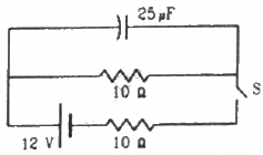
Initially, the switch S was closed; so, the capacitor was getting charged. Also, the two resistors are connected in parallel. The equivalent resistance of the circuit,
Initially, the switch was closed and the capacitor was getting charged. So, the two resistances were in parallel connection.
Hence, their effective resistance will be 5 Ω.
Potential difference across the 10 Ω resistance,
When the switch is opened, the decay of charge through the capacitor,
Current in the 10 Ω resistor,
Q.81. A capacitor of capacitance 100 μF is connected across a battery of emf 6 V through a resistance of 20 kΩ for 4 s. The battery is then replaced by a thick wire. What will be the charge on the capacitor 4 s after the battery is disconnected?
Given:-
Capacitance of capacitor ,C = 100 μF
Emf of battery ,E = 6V
Resistance ,R = 20 kΩ
Time for charging , t1 = 4 s
Time for discharging ,t2 = 4 s
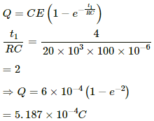
During charging of the capacitor, the growth of charge across it,
This is the amount of charge developed on the capacitor after 4s.
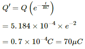
During discharging of the capacitor, the decay of charge across it,
Q.82. Consider the situation shown in figure. The switch is closed at t = 0 when the capacitors are uncharged. Find the charge on the capacitor C1 as a function of time t.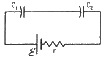
The two capacitors are connected in series. Their equivalent capacitance,
The growth of charge in the capacitors,
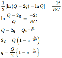
Q.83. A capacitor of capacitance C is given a charge Q. At t = 0, it is connected to an uncharged capacitor of equal capacitance through a resistance R. Find the charge on the second capacitor as a function of time.
Given:-
Initial charge on first capacitor = Q
Let q be the charge on the second capacitor after time t.
According to the principle of conservation of charge, charge on the first capacitor after time t = Q - q.
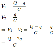
Let V1 be the potential difference across the first capacitor and V2 be the potential difference across the second capacitor after time t. Then,
The current through the circuit after time t,
Integrating both sides within the limits time =0 to t and charge on the second capacitor varying from q = 0 to q, we get:-
Q.84. A capacitor of capacitance C is given a charge Q. At t = 0, it is connected to an ideal battery of emf ε through a resistance R. Find the charge on the capacitor at time t.
Given:-
Initial charge given to the capacitor = Q
When the capacitor is connected to a battery, it will charge through the battery. The initial charge will also decay.
The growth of charge across the capacitor due to the battery of emf E,
The decay of charge through the capacitor,
The net charge on the capacitor at any time t,
|
134 docs
|
FAQs on HC Verma Questions and Solutions: Chapter 32: Electric Current in Conductors- 3 - HC Verma Solutions - JEE
| 1. What is electric current and how is it defined in conductors? |  |
| 2. What factors affect the magnitude of electric current in a conductor? |  |
| 3. What is Ohm's law and how is it expressed mathematically? |  |
| 4. What is the difference between a conductor and an insulator in terms of electric current flow? |  |
| 5. How does the thickness and length of a conductor affect its resistance? |  |


