Electrical Engineering (EE) Exam  >  Electrical Engineering (EE) Notes  >  GATE Notes & Videos for Electrical Engineering  >  Inductance & Resistance of Transmission Lines

Inductance & Resistance of Transmission Lines | GATE Notes & Videos for Electrical Engineering - Electrical Engineering (EE) PDF Download

Inductance in Transmission Line

Reason of Transmission Line Inductance

Generally, electric power is transmitted through the transmission line with AC high voltage and current. High valued alternating current while flowing through the conductor sets up magnetic flux of high strength with alternating nature. This high valued alternating magnetic flux makes a linkage with other adjacent conductors parallel to the main conductor. Flux linkage in a conductor happens internally and externally. Internally flux linkage is due to self-current and externally flux linkage due to external flux. Now the term inductance is closely related to the flux linkage, denoted by λ. Suppose a coil with N number of turn is linked by flux Φ due to current I, then,

Inductance & Resistance of Transmission Lines | GATE Notes & Videos for Electrical Engineering - Electrical Engineering (EE)

But for transmission line N = 1. We have to calculate only the value of flux Φ, and hence, we can get the transmission line inductance.


Calculation of Inductance of Single Conductor

Calculation of Internal Inductance due to Internal Magnetic Flux of a Conductor

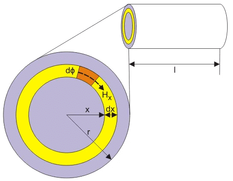
Suppose a conductor is carrying current I through its length l, x is the internal variable radius of the conductor and r is the original radius of the conductor. Now the cross-sectional area with respect to radius x is πx2 square – unit and current Ix is flowing through this cross-sectional area. So the value of Ican be expressed in term of original conductor current I and cross-sectional area πr2 square – unit

Inductance & Resistance of Transmission Lines | GATE Notes & Videos for Electrical Engineering - Electrical Engineering (EE)

Inductance & Resistance of Transmission Lines | GATE Notes & Videos for Electrical Engineering - Electrical Engineering (EE)

Now consider small thickness dx with the 1m length of the conductor, where Hx is the magnetizing force due to current Ix around the area πx2.

Inductance & Resistance of Transmission Lines | GATE Notes & Videos for Electrical Engineering - Electrical Engineering (EE)

And magnetic flux density Bx = μHx, where μ is the permeability of this conductor. Again, µ = µ0µr. If it is considered that the relative permeability of this conductor µr = 1, then µ = µ0. Hence, here Bx = μ0 Hx.

Inductance & Resistance of Transmission Lines | GATE Notes & Videos for Electrical Engineering - Electrical Engineering (EE)

dφ for small strip dx is expressed by

Inductance & Resistance of Transmission Lines | GATE Notes & Videos for Electrical Engineering - Electrical Engineering (EE)

Here entire cross-sectional area of the conductor does not enclose the above expressed flux. The ratio of the cross sectional area inside the circle of radius x to the total cross section of the conductor can be thought about as fractional turn that links the flux. Therefore the flux linkage is

Inductance & Resistance of Transmission Lines | GATE Notes & Videos for Electrical Engineering - Electrical Engineering (EE)

Now, the total flux linkage for the conductor of 1m length with radius r is given by

Inductance & Resistance of Transmission Lines | GATE Notes & Videos for Electrical Engineering - Electrical Engineering (EE)

Hence, the internal inductance is

Inductance & Resistance of Transmission Lines | GATE Notes & Videos for Electrical Engineering - Electrical Engineering (EE)

External Inductance due to External Magnetic Flux of a Conductor

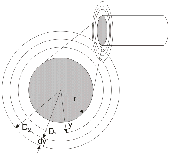
Let us assume, due to skin effect conductor current I is concentrated near the surface of the conductor. Consider, the distance y is taken from the center of the conductor making the external radius of the conductor.
Inductance & Resistance of Transmission Lines | GATE Notes & Videos for Electrical Engineering - Electrical Engineering (EE)

Hy is the magnetizing force and By is the magnetic field density at y distance per unit length of the conductor.

Now,

Inductance & Resistance of Transmission Lines | GATE Notes & Videos for Electrical Engineering - Electrical Engineering (EE)

Let us assume magnetic flux dφ is present within the thickness dy from D1 to D2 for 1 m length of the conductor as per the figure.

Inductance & Resistance of Transmission Lines | GATE Notes & Videos for Electrical Engineering - Electrical Engineering (EE)

As the total current I is assumed to flow in the surface of the conductor, so the flux linkage dλ is equal to dφ.

Inductance & Resistance of Transmission Lines | GATE Notes & Videos for Electrical Engineering - Electrical Engineering (EE)

But we have to consider the flux linkage from conductor surface to any external distance, i.e. r to D

So,

Inductance & Resistance of Transmission Lines | GATE Notes & Videos for Electrical Engineering - Electrical Engineering (EE)

Inductance & Resistance of Transmission Lines | GATE Notes & Videos for Electrical Engineering - Electrical Engineering (EE)

Inductance & Resistance of Transmission Lines | GATE Notes & Videos for Electrical Engineering - Electrical Engineering (EE)

Inductance & Resistance of Transmission Lines | GATE Notes & Videos for Electrical Engineering - Electrical Engineering (EE)

Inductance & Resistance of Transmission Lines | GATE Notes & Videos for Electrical Engineering - Electrical Engineering (EE)

Inductance of Two Wire Single Phase Transmission Line

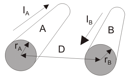
Suppose conductor A of radius rA carries a current of IA in opposite direction of current IB through the conductor B of radius rB. Conductor A is at a distance D from conductor B and both are of length l. They are in close vicinity with each other so that flux linkage takes place in both of the conductors due to their electromagnetic effects.
Inductance & Resistance of Transmission Lines | GATE Notes & Videos for Electrical Engineering - Electrical Engineering (EE)

Let us consider the magnitude of current in both conductors are same and hence IA = – IB,

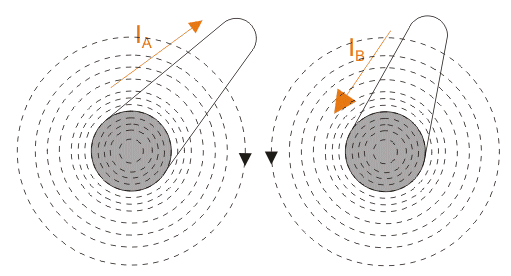
Now, total flux linkage in conductor A = flux linkage by self-current of conductor A + flux linkage on conductor A due to current in the conductor B.

Similarly, flux linkage in conductor B = flux linkage by self-current of conductor B + flux linkage on conductor B due to current through conductor A.
Inductance & Resistance of Transmission Lines | GATE Notes & Videos for Electrical Engineering - Electrical Engineering (EE)

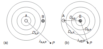
Now if we consider a point P in close vicinity both conductor A and B, the flux linkage at point P would be, flux linkage at point P for current carrying conductor A + flux linkage at point P for current carrying conductor B i.e.

λp = λAP + λBP

Now,

λ= λAP + λBPAAP + λABP) +(λBAP + λBBP)

……… shown in the figure below in figure (a) and (b).
Inductance & Resistance of Transmission Lines | GATE Notes & Videos for Electrical Engineering - Electrical Engineering (EE)

  • λAAP is the flux linkage at point P for conductor A due to current through conductor A itself.
  • λABP is the flux linkage at point P for conductor A due to current through conductor B.
  • λBAP is the flux linkage at point P for conductor B due to current through conductor A.
  • λBBP is the flux linkage at point P for conductor B due to current through conductor B itself.

Inductance & Resistance of Transmission Lines | GATE Notes & Videos for Electrical Engineering - Electrical Engineering (EE)

Inductance & Resistance of Transmission Lines | GATE Notes & Videos for Electrical Engineering - Electrical Engineering (EE)

λABP and λBAP are negative in value because the directions current are opposite with respect to each other.
So,
λ= λAP + λBP = (λAAP + λABP) +(λBAP + λBBP)

Inductance & Resistance of Transmission Lines | GATE Notes & Videos for Electrical Engineering - Electrical Engineering (EE)

Inductance & Resistance of Transmission Lines | GATE Notes & Videos for Electrical Engineering - Electrical Engineering (EE)

If we consider that both conductor are with same radius, i.e. rA = rB = r and point P is shifted to infinite distance then we can write that

Inductance & Resistance of Transmission Lines | GATE Notes & Videos for Electrical Engineering - Electrical Engineering (EE)

Therefore, inductance per phase 

Inductance & Resistance of Transmission Lines | GATE Notes & Videos for Electrical Engineering - Electrical Engineering (EE)

If conductor A becomes bundled conductor, then its geometrical mean radius (GMR) will be calculated for n number of conductors per bundle.

Inductance & Resistance of Transmission Lines | GATE Notes & Videos for Electrical Engineering - Electrical Engineering (EE)

Where, d is the distance between the central axis of conductors within the bundle.

Inductance in Three Phase Transmission Line

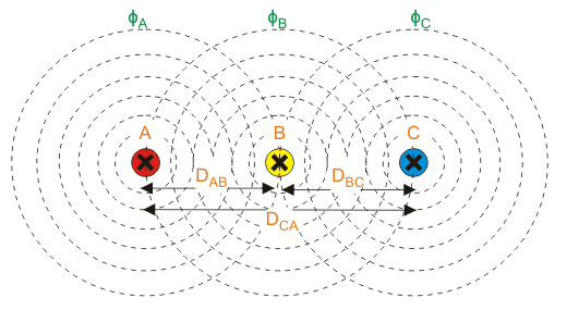
In the three phase transmission line, three conductors are parallel to each other. The direction of the current is same through each of the conductors.

Let us consider conductor A produces magnetic flux φA,

Conductor B produces magnetic flux φB,

And conductor C produces magnetic flux φC.

When they carry the current of the same magnitude “I”, they are in flux linkage with each other.
Inductance & Resistance of Transmission Lines | GATE Notes & Videos for Electrical Engineering - Electrical Engineering (EE)

Now, let us consider a point P near three conductors. So, flux linkage at point P due to current through conductor A is,

λAPAAP + λABP + λACP

Inductance & Resistance of Transmission Lines | GATE Notes & Videos for Electrical Engineering - Electrical Engineering (EE)

Flux linkage at point P for conductor A due to current through conductor A =

Inductance & Resistance of Transmission Lines | GATE Notes & Videos for Electrical Engineering - Electrical Engineering (EE)

Flux linkage at point P for conductor A due to current through conductor B =

Inductance & Resistance of Transmission Lines | GATE Notes & Videos for Electrical Engineering - Electrical Engineering (EE)

Flux linkage at point P for conductor A due to current through conductor C =

Inductance & Resistance of Transmission Lines | GATE Notes & Videos for Electrical Engineering - Electrical Engineering (EE)

Therefore, flux linkage at point P for conductor A,

Inductance & Resistance of Transmission Lines | GATE Notes & Videos for Electrical Engineering - Electrical Engineering (EE)

Inductance & Resistance of Transmission Lines | GATE Notes & Videos for Electrical Engineering - Electrical Engineering (EE)

As,

DAP = DBP=DCP

and

IA+IB+IC= 0

in balanced system, then we can write that

IA= -IB - IC

Inductance & Resistance of Transmission Lines | GATE Notes & Videos for Electrical Engineering - Electrical Engineering (EE)

Inductance & Resistance of Transmission Lines | GATE Notes & Videos for Electrical Engineering - Electrical Engineering (EE)

Inductance & Resistance of Transmission Lines | GATE Notes & Videos for Electrical Engineering - Electrical Engineering (EE)

Inductance & Resistance of Transmission Lines | GATE Notes & Videos for Electrical Engineering - Electrical Engineering (EE)

Similarly,

Inductance & Resistance of Transmission Lines | GATE Notes & Videos for Electrical Engineering - Electrical Engineering (EE)

and

Inductance & Resistance of Transmission Lines | GATE Notes & Videos for Electrical Engineering - Electrical Engineering (EE)

If we arrange them in matrix form, then we get

Inductance & Resistance of Transmission Lines | GATE Notes & Videos for Electrical Engineering - Electrical Engineering (EE)

Where, λA, λB, λC are the total flux linkages of conductor A, B and C.

LAA, LBB and LCC are the self inductances of conductor A, B and C.

LAB, LAC, LBC, LBA, LCA, LCB are the mutual inductances of between conductors A, B and C.

Again balanced system

DAB =DBC = DCA =D

And

IA + IB + IC = 0

In balanced system, then we can write that

IA = - IB - IC

Inductance & Resistance of Transmission Lines | GATE Notes & Videos for Electrical Engineering - Electrical Engineering (EE)

Inductance & Resistance of Transmission Lines | GATE Notes & Videos for Electrical Engineering - Electrical Engineering (EE)

Similarly,

Inductance & Resistance of Transmission Lines | GATE Notes & Videos for Electrical Engineering - Electrical Engineering (EE)

So, inductance per meter per phase,

Inductance & Resistance of Transmission Lines | GATE Notes & Videos for Electrical Engineering - Electrical Engineering (EE)

The document Inductance & Resistance of Transmission Lines | GATE Notes & Videos for Electrical Engineering - Electrical Engineering (EE) is a part of the Electrical Engineering (EE) Course GATE Notes & Videos for Electrical Engineering.
All you need of Electrical Engineering (EE) at this link: Electrical Engineering (EE)
27 videos|328 docs

Top Courses for Electrical Engineering (EE)

FAQs on Inductance & Resistance of Transmission Lines - GATE Notes & Videos for Electrical Engineering - Electrical Engineering (EE)

1. What is inductance in transmission lines?
Ans. Inductance in transmission lines refers to the property of a transmission line that opposes any change in the flow of current. It is caused by the magnetic fields formed around the conductors when current flows through them. Inductance is represented by the symbol L and is measured in henries (H).
2. How does inductance affect transmission lines?
Ans. Inductance affects transmission lines by causing a delay in the transmission of electrical signals. It leads to a phenomenon called inductive reactance, which increases with frequency. This inductive reactance can cause signal distortion, phase shifts, and power losses in the transmission line.
3. How is inductance calculated in transmission lines?
Ans. Inductance in transmission lines can be calculated using various formulas, depending on the geometry of the line. For a simple two-wire transmission line, the inductance can be calculated using the formula L = (μ₀μᵣ/2π) * ln(D/d), where μ₀ is the permeability of free space, μᵣ is the relative permeability of the medium between the conductors, D is the distance between the conductors, and d is the diameter of the conductors.
4. What is the significance of resistance in transmission lines?
Ans. Resistance in transmission lines refers to the property that opposes the flow of current due to the resistance of the conductive material. It leads to power losses in the form of heat and affects the efficiency of the transmission line. Resistance is represented by the symbol R and is measured in ohms (Ω).
5. How does resistance affect the performance of transmission lines?
Ans. Resistance affects the performance of transmission lines by causing power losses and voltage drops. These losses increase with the distance traveled by the transmission line and the amount of current flowing through it. High resistance can lead to reduced efficiency, increased heating of the conductors, and voltage drops that can affect the quality of the transmitted signals.
27 videos|328 docs
Download as PDF
Explore Courses for Electrical Engineering (EE) exam

Top Courses for Electrical Engineering (EE)

Signup for Free!
Signup to see your scores go up within 7 days! Learn & Practice with 1000+ FREE Notes, Videos & Tests.
10M+ students study on EduRev
Related Searches

Free

,

video lectures

,

Summary

,

Inductance & Resistance of Transmission Lines | GATE Notes & Videos for Electrical Engineering - Electrical Engineering (EE)

,

MCQs

,

Previous Year Questions with Solutions

,

Objective type Questions

,

ppt

,

shortcuts and tricks

,

Viva Questions

,

practice quizzes

,

Semester Notes

,

Inductance & Resistance of Transmission Lines | GATE Notes & Videos for Electrical Engineering - Electrical Engineering (EE)

,

Inductance & Resistance of Transmission Lines | GATE Notes & Videos for Electrical Engineering - Electrical Engineering (EE)

,

Sample Paper

,

past year papers

,

study material

,

pdf

,

Extra Questions

,

mock tests for examination

,

Important questions

,

Exam

;