Introduction to Hardware Description Languages - 1 | Embedded Systems (Web) - Computer Science Engineering (CSE) PDF Download

Introduction to Hardware Description Languages - I
Instructional Objectives
At the end of the lesson the student should be able to
• Describe a digital IC design flow and explain its various abstraction levels.
• Explain the need for a hardware description language in the IC desing flow
• Model simple hardware devices at various levels of abstraction using Verilog (Gate/Switch/Behavioral)
• Write Verilog codes meeting the prescribed requirement at a specified level
1.1 Introduction
1.1.1 What is a HDL and where does Verilog come?
HDL is an abbreviation of Hardware Description Language. Any digital system can be represented in a REGISTER TRANSFER LEVEL (RTL) and HDLs are used to describe this RTL. Verilog is one such HDL and it is a general-purpose language –easy to learn and use. Its syntax is similar to C. The idea is to specify how the data flows between registers and how the design processes the data. To define RTL, hierarchical design concepts play a very significant role. Hierarchical design methodology facilitates the digital design flow with several levels of abstraction. Verilog HDL can utilize these levels of abstraction to produce a simplified and efficient representation of the RTL description of any digital design. For example, an HDL might describe the layout of the wires, resistors and transistors on an Integrated Circuit (IC) chip, i.e., the switch level or, it may describe the design at a more micro level in terms of logical gates and flip flops in a digital system, i.e., the gate level. Verilog supports all of these levels.
1.1.2 Hierarchy of design methodologies
Bottom-Up Design
The traditional method of electronic design is bottom-up (designing from transistors and moving to a higher level of gates and, finally, the system). But with the increase in design complexity traditional bottom-up designs have to give way to new structural, hierarchical design methods.
Top-Down Design
For HDL representation it is convenient and efficient to adapt this design-style. A real top-down design allows early testing, fabrication technology independence, a structured system design and offers many other advantages. But it is very difficult to follow a pure top-down design. Due to this fact most designs are mix of both the methods, implementing some key elements of both design styles.
1.1.3 Hierarchical design concept and Verilog
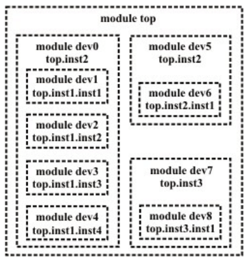
To follow the hierarchical design concepts briefly mentioned above one has to describe the design in terms of entities called MODULES.
A module is the basic building block in Verilog. It can be an element or a collection of low level design blocks. Typically, elements are grouped into modules to provide common functionality used in places of the design through its port interfaces, but hides the internal implementation.
1.1.4 Abstraction Levels
• Behavioral level
• Register-Transfer Level
• Gate Level
• Switch level
Behavioral or algorithmic Level
This level describes a system by concurrent algorithms (Behavioral). Each algorithm itself is sequential meaning that it consists of a set of instructions that are executed one after the other. ‘initial’, ‘always’ ,‘functions’ and ‘tasks’ blocks are some of the elements used to define the system at this level. The intricacies of the system are not elaborated at this stage and only the functional description of the individual blocks is prescribed. In this way the whole logic synthesis gets highly simplified and at the same time more efficient.
Register-Transfer Level
Designs using the Register-Transfer Level specify the characteristics of a circuit by operations and the transfer of data between the registers. An explicit clock is used. RTL design contains exact timing possibility, operations are scheduled to occur at certain times. Modern definition of a RTL code is "Any code that is synthesizable is called RTL code".
Gate Level
Within the logic level the characteristics of a system are described by logical links and their timing properties. All signals are discrete signals. They can only have definite logical values (`0', `1', `X', `Z`). The usable operations are predefined logic primitives (AND, OR, NOT etc gates). It must be indicated here that using the gate level modeling may not be a good idea in logic design. Gate level code is generated by tools like synthesis tools in the form of netlists which are used for gate level simulation and for backend.
Switch Level
This is the lowest level of abstraction. A module can be implemented in terms of switches, storage nodes and interconnection between them. However, as has been mentioned earlier, one can mix and match all the levels of abstraction in a design. RTL is frequently used for Verilog description that is a combination of behavioral and dataflow while being acceptable for synthesis.
Instances A module provides a template from where one can create objects. When a module is invoked Verilog creates a unique object from the template, each having its own name, variables, parameters and I/O interfaces. These are known as instances.
1.1.5 The Design Flow
This block diagram describes a typical design flow for the description of the digital design for both ASIC and FPGA realizations.
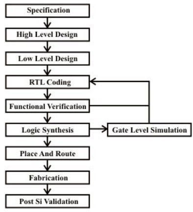
Specification
This is the stage at which we define the important parameters of the system that has to be designed. For example for designing a counter one has to decide its bit-size, whether it should have synchronous reset whether it must be active high enable etc.
High Level Design
This is the stage at which one defines various blocks in the design in the form of modules and instances. For instance for a microprocessor a high level representation means splitting the design into blocks based on their function. In this case the various blocks are registers, ALU, Instruction Decode, Memory Interface, etc
Micro Design/Low level design
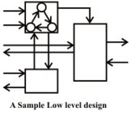
Low level design or Micro design is the phase in which, designer describes how each block is implemented. It contains details of State machines, counters, Mux, decoders, internal registers. For state machine entry you can use either Word, or special tools like State CAD. It is always a good idea if waveform is drawn at various interfaces. This is the phase, where one spends lot of time. A sample low level design is indicated in the figure below.
RTL Coding
In RTL coding, Micro Design is converted into Verilog/VHDL code, using synthesizable constructs of the language. Normally, vim editor is used, and conTEXT, Nedit and Emacs are other choices.
Simulation
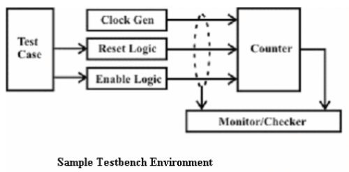
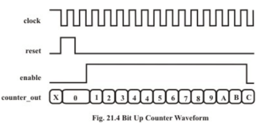
Simulation is the process of verifying the functional characteristics of models at any level of abstraction. We use simulators to simulate the the Hardware models. To test if the RTL code meets the functional requirements of the specification, see if all the RTL blocks are functionally correct. To achieve this we need to write testbench, which generates clk, reset and required test vectors. A sample testbench for a counter is as shown below. Normally, we spend 60-70% of time in verification of design.
We use waveform output from the simulator to see if the DUT (Device Under Test) is functionally correct. Most of the simulators come with waveform viewer, as design becomes complex, we write self checking testbench, where testbench applies the test vector, compares the output of DUT with expected value. There is another kind of simulation, called timing simulation, which is done after synthesis or after P&R (Place and Route). Here we include the gate delays and wire delays and see if DUT works at the rated clock speed. This is also called as SDF simulation or gate level simulation
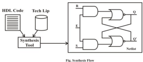
Synthesis
Synthesis is the process in which a synthesis tool like design compiler takes in the RTL in Verilog or VHDL, target technology, and constrains as input and maps the RTL to target technology primitives. The synthesis tool after mapping the RTL to gates, also does the minimal amount of timing analysis to see if the mapped design is meeting the timing requirements. (Important thing to note is, synthesis tools are not aware of wire delays, they know only gate delays). After the synthesis there are a couple of things that are normally done before passing the netlist to backend (Place and Route)
• Verification: Check if the RTL to gate mapping is correct
. • Scan insertion: Insert the scan chain in the case of ASIC.
Place & Route Gate-level netlist from the synthesis tool is taken and imported into place and route tool in the Verilog netlist format. All the gates and flip-flops are placed, Clock tree synthesis and reset is routed. After this each block is routed. Output of the P&R tool is a GDS file, this file is used by a foundry for fabricating the ASIC. Normally the P&R tool are used to output the SDF file, which is back annotated along with the gatelevel netlist from P&R into static analysis tool like Prime Time to do timing analysis.
Post Silicon Validation
Once the chip (silicon) is back from fabrication, it needs to be put in a real environment and tested before it can be released into market. Since the speed of simulation with RTL is very slow (number clocks per second), there is always a possibility to find a bug
1.2 Verilog HDL: Syntax and Semantics 1.2.1 Lexical Conventions
The basic lexical conventions used by Verilog HDL are similar to those in the C programming language. Verilog HDL is a case-sensitive language. All keywords are in lowercase.
1.2.2 Data Types
Verilog Language has two primary data types :
• Nets - represents structural connections between components.
• Registers - represent variables used to store data.
Every signal has a data type associated with it. Data types are:
• Explicitly declared with a declaration in the Verilog code.
• Implicitly declared with no declaration but used to connect structural building blocks in the code. Implicit declarations are always net type "wire" and only one bit wide.
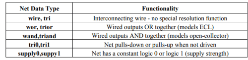
Types of Net
Each net type has functionality that is used to model different types of hardware (such as PMOS, NMOS, CMOS, etc).This has been tabularized as follows:
Register Data Types
• Registers store the last value assigned to them until another assignment statement changes their value.
• Registers represent data storage constructs.
• Register arrays are called memories.
• Register data types are used as variables in procedural blocks.
• A register data type is required if a signal is assigned a value within a procedural block
• Procedural blocks begin with keyword initial and always.
Some common data types are listed in the following table:
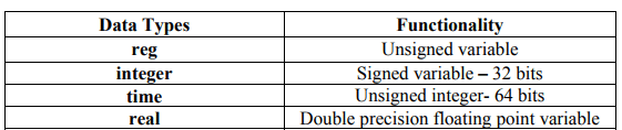
1.2.3 Apart from these there are vectors, integer, real & time register data types.
Some examples are as follows:
Integer
integer counter; // general purpose variable used as a counter.
initial counter= -1; // a negative one is stored in the counter
Real real delta; // Define a real variable called delta.
initial
begin
delta= 4e10; // delta is assigned in scientific notation
delta = 2.13; // delta is assigned a value 2.13
end
integer i; // define an integer I;
initial i = delta ; // I gets the value 2(rounded value of 2.13)
Time time save_sim_time; // define a time variable save_sim_time
initial save_sim_time = $time; //
save the current simulation time.
n.b. $time is invoked to get the current simulation time
Arrays
integer count [0:7]; // an array of 8 count variables
reg [4:0] port_id[0:7]; // Array of 8 port _ids, each 5 bit wide
integer matrix[4:0] [0:255] ; // two dimensional array of integers.
1.2.4 Some Constructs Using Data Types
Memories
Memories are modeled simply as one dimensional array of registers each element of the array is know as an element of word and is addressed by a single array index. reg membit [0:1023] ; // memory meme1bit with 1K 1- bit words reg [7:0] membyte [0:1023]; memory membyte with 1K 8 bit words membyte [511] // fetches 1 byte word whose address is 511.
Strings
A string is a sequence of characters enclosed by double quotes and all contained on a single line. Strings used as operands in expressions and assignments are treated as a sequence of eight-bit ASCII values, with one eight-bit ASCII value representing one character. To declare a variable to store a string, declare a register large enough to hold the maximum number of characters the variable will hold. Note that no extra bits are required to hold a termination character; Verilog does not store a string termination character. Strings can be manipulated using the standard operators. When a variable is larger than required to hold a value being assigned, Verilog pads the contents on the left with zeros after the assignment. This is consistent with the padding that occurs during assignment of non-string values. Certain characters can be used in strings only when preceded by an introductory character called an escape character. The following table lists these characters in the right-hand column with the escape sequence that represents the character in the left-hand column.
Modules
• Module are the building blocks of Verilog designs
• You create design hierarchy by instantiating modules in other modules.
• An instance of a module can be called in another, higher-level module.
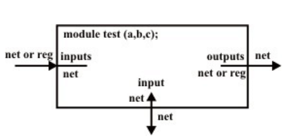
Ports
• Ports allow communication between a module and its environment.
• All but the top-level modules in a hierarchy have ports.
• Ports can be associated by order or by name.
You declare ports to be input, output or inout. The port declaration syntax is : input [range_val:range_var] list_of_identifiers; output [range_val:range_var] list_of_identifiers; inout [range_val:range_var] list_of_identifiers;
Schematic
1.2.5 Port Connection Rules
• Inputs : internally must always be type net, externally the inputs can be connected to variable reg or net type
• Outputs : internally can be type net or reg, externally the outputs must be connected to a variable net type.
• Inouts : internally or externally must always be type net, can only be connected to a variable net type.
• Width matching: It is legal to connect internal and external ports of different sizes. But beware, synthesis tools could report problems.
• Unconnected ports : unconnected ports are allowed by using a ","
• The net data types are used to connect structure
• A net data type is required if a signal can be driven a structural connection.
Example – Implicit
dff u0 ( q,,clk,d,rst,pre); // Here second port is not connected
Example – Explicit
dff u0 (.q (q_out), .q_bar (), .clk (clk_in), .d (d_in), .rst (rst_in), .pre (pre_in)); // Here second port is not connected.
|
50 videos|69 docs|65 tests
|


practice quizzes
,mock tests for examination
,Summary
,Objective type Questions
,MCQs
,video lectures
,Semester Notes
,Important questions
,Introduction to Hardware Description Languages - 1 | Embedded Systems (Web) - Computer Science Engineering (CSE)
,Introduction to Hardware Description Languages - 1 | Embedded Systems (Web) - Computer Science Engineering (CSE)
,Sample Paper
,Exam
,Extra Questions
,shortcuts and tricks
,ppt
,past year papers
,Previous Year Questions with Solutions
,Free
,Viva Questions
,Introduction to Hardware Description Languages - 1 | Embedded Systems (Web) - Computer Science Engineering (CSE)
,study material
;


Introduction to Hardware Description Languages - 1 Free PDF Download
Importance of Introduction to Hardware Description Languages - 1
Introduction to Hardware Description Languages - 1 Notes
Introduction to Hardware Description Languages - 1 Computer Science Engineering (CSE) Questions
Study Introduction to Hardware Description Languages - 1 on the App
|
© EduRev
|
Education Revolution
|


|


