Introduction to Laminar Boundary Layers - 1 | Fluid Mechanics for Mechanical Engineering PDF Download
| Table of contents |

|
| Introduction |

|
| Boundary Layer Equations |

|
| About the boundary layer |

|
| Order of Magnitude Analysis |

|
| Boundary Layer Coordinates |

|
| Application of Boundary Layer Theory |

|
| Shooting Technique |

|
Introduction
- The boundary layer of a flowing fluid is the thin layer close to the wall
- In a flow field, viscous stresses are very prominent within this layer.
- Although the layer is thin, it is very important to know the details of flow within it.
- The main-flow velocity within this layertends to zero while approaching the wall (no-slip condition).
- Also the gradient of this velocity component in a direction normal to the surface is large as compared to the gradient in the streamwise direction.
Boundary Layer Equations
- In 1904, Ludwig Prandtl, the well known German scientist, introduced the concept of boundary layer andderived the equations for boundary layer flowby correct reduction of Navier-Stokes equations.
- He hypothesized that for fluids having relatively small viscosity, the effect of internal friction in the fluid is significant only in a narrow region surrounding solid boundaries or bodies over which the fluid flows.
- Thus, close to the body is the boundary layer where shear stresses exert an increasingly larger effect on the fluid asone moves from free stream towards the solid boundary.
- However, outside the boundary layer where the effect of the shear stresses on the flow is small compared to values inside the boundary layer (since the velocity gradient du/dyis negligible),---------
- the fluid particles experience no vorticityand therefore,
- the flow is similar to a potential flow.
- Hence, the surface at the boundary layer interface is a rather fictitious one, that divides rotational and irrotational flow. Fig 28.1 shows Prandtl's model regarding boundary layer flow.
- Hence with the exception of the immediate vicinity of the surface, the flow is frictionless (inviscid) and the velocity is U (the potential velocity).
- In the region, very near to the surface (in the thin layer), there is friction in the flow which signifies that the fluid is retarded until it adheres to the surface (no-slip condition).
- The transition of the mainstream velocity from zero at the surface (with respect to the surface) to full magnitude takes place across the boundary layer.
About the boundary layer
- Boundary layer thickness is δwhich is a function of the coordinate direction x .
- The thickness is considered to be very small compared to the characteristic lengthL of the domain.
- In the normal direction, within this thin layer, the gradientdu/dyis very large compared to the gradient in the flow directiondu /dx.
Now we take up the Navier-Stokes equations for : steady, two dimensional, laminar, incompressible flows.
Considering the Navier-Stokes equations together with the equation of continuity, the following dimensional form is obtained. 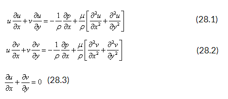
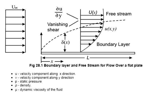
- u - velocity component along x direction.
- v - velocity component along y direction
- p - static pressure
- ρ - density.
- μ - dynamic viscosity of the fluid
- The equations are now non-dimensionalised.
- The length and the velocity scales are chosen as L and
 respectively.
 - The non-dimensional variables are:


- where U∞ is the dimensional free stream velocity and the pressure is non-dimensionalised by twice the dynamic pressure

Using these non-dimensional variables, the Eqs (28.1) to (28.3) become 
where the Reynolds number, 
Order of Magnitude Analysis
- Let us examine what happens to the u velocity as we go across the boundary layer.
At the wallthe u velocity is zero [ with respect to the wall and absolute zero for a stationary wall (which is normally implied if not stated otherwise)].
The value of u on the inviscid side, that is on the free stream side beyond the boundary layer is U.
For the case of external flow over a flat plate, this U is equal to U∞. - Based on the above, we can identify the following scales for the boundary layer variables:
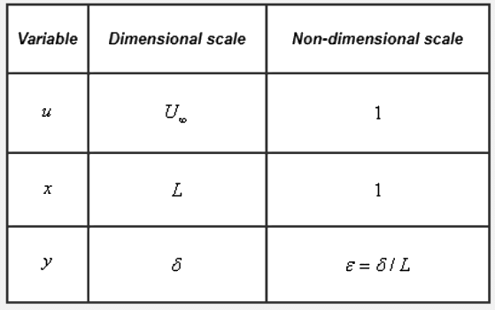
- The symbol ε describes a value much smaller than 1.
- Now we analyze equations 28.4 - 28.6 and look at the order of magnitude of each individual term Eq 28.6 - the continuity equation.
- One general rule of incompressible fluid mechanics is that we are not allowed to drop any term from the continuity equation.
- From the scales of boundary layer variables, the derivative ∂u/∂x** is of the order 1.
- The second term in the continuity equation ∂v/∂y** should also be of the order 1. The reason being v* has to be of the order ε because y* becomes at its ε(= δ/L) maximum.
- Eq 28.4 - x direction momentum equation
- Inertia terms are of the order 1.
- ∂²u/∂x² is of the order 1.
- ∂²u/∂y² is of the order (1/ε²).
However after multiplication with 1/Re, the sum of the two second order derivatives should produce at least one term which is of the same order of magnitude as the inertia terms. This is possible only if the Reynolds number (Re) is of the order of .
It follows from that will not exceed the order of 1 so as to be in balance with the remaining term.
Finally, Eqs (28.4), (28.5) and (28.6) can be rewritten as 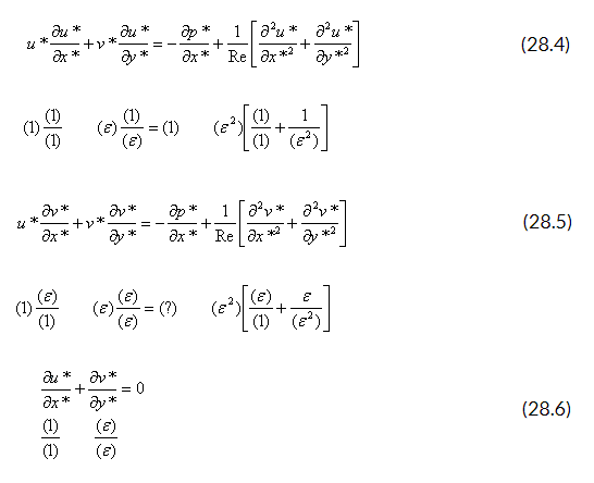 As a consequence of the order of magnitude analysis, ∂²u/∂x² can be dropped from the x direction momentum equation, because on multiplication with 1/Re it assumes the smallest order of magnitude.
Eq 28.5 - y direction momentum equation.
- All the terms of this equation are of a smaller magnitude than those of Eq. (28.4).
This equation can only be balanced if ∂p/∂y is of the same order of magnitude as other terms.
- Thus they momentum equation reduces to

- This means that the pressure across the boundary layer does not change. The pressure is impressed on the boundarylayer, and its value is determined by hydrodynamic considerations.
- This also implies that the pressure p is only a function of x. The pressure forces on a body are solelydetermined by theinviscid flow outside the boundary layer.
- The application of Eq. (28.4) at the outer edge of boundary layer gives
 In dimensional form, this can be written as
 On integrating Eq ( 28.8b) the well known Bernoulli's equation is obtained
 Finally, it can be said that by the order of magnitude analysis, the Navier-Stokes equations are simplified into equations given below.

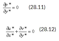
These are known as Prandtl's boundary-layer equations.
The available boundary conditions are:
Solid surface
or 
Outer edge of boundary-layer

The unknown pressure p in the x-momentum equation can be determined from Bernoulli's Eq. (28.9), if the inviscid velocity distribution U(x) is also known.
We solve the Prandtl boundary layer equations for u* (x,y)and v* (x,y) with U obtained from the outer inviscid flow analysis. The equations are solved by commencing at the leading edge of the body and moving downstream to the desired location
- it allows the no-slip boundary condition to be satisfied which constitutes a significant improvement over the potential flow analysis while solving real fluid flow problems.
- The Prandtl boundary layer equations are thus a simplification of the Navier-Stokes equations.
Boundary Layer Coordinates
- The boundary layer equations derived are in Cartesian coordinates.
- The Velocity components u and v represent x and y direction velocities respectively.
- For objects with small curvature, these equations can be used with -
(i)x coordinate : streamwise directio
(ii)y coordinate : normal component - They are called Boundary Layer Coordinates
Application of Boundary Layer Theory
- The Boundary-Layer Theory is not valid beyond the point of separation.
- At the point of separation, boundary layer thickness becomes quite large for the thin layer approximation to be valid.
- It is important to note that boundary layer theory can be used to locate the point of seperation itself.
- In applying the boundary layer theory although U is the free-stream velocity at the outer edge of the boundary layer, it is interpreted as the fluid velocity at the wall calculated from inviscid flow considerations ( known as Potential Wall Velocity)
- Mathematically, application of the boundary - layer theory converts the character of governing Navier-Stroke equations from elliptic to parabolic
- This allows the marching in flow direction, as the solution at any location is independent of the conditions farther downstream
Blasius Flow Over A Flat Plate
- The classical problem considered by H. Blasius was
- Two-dimensional, steady, incompressible flow over a flat plate at zero angle of incidence with respect to the uniform stream of velocity U∞.
- The fluid extends to infinity in all directions from the plate.
- Blasius wanted to determine
(a) the velocity field solely within the boundary layer,
(b) the boundary layer thickness(δ),
(c) the shear stress distribution on the plate, and
(d) the drag force on the plate. - The Prandtl boundary layer equations in the case under consideration are
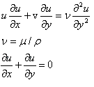 The boundary conditions are

- Note that the substitution of the term
 in the original boundary layer momentum equation in terms of the free stream velocity produces
  which is equal to zero.
 - Hence the governing Eq. (28.15) does not contain any pressure-gradient term.
- However, the characteristic parameters of this problem are U∞, x, v,y that is, u = u U∞, x, v,y
- This relation has five variablesU∞, x, v,y.
- It involves two dimensions, length and time.
- Thus it can be reduced to a dimensionless relation in terms of (5-2) =3 quantities ( Buckingham Pi Theorem)
- Thus a similarity variables can be used to find the solution
- Such flow fields are called self-similar flow field .
Law of Similarity for Boundary Layer Flows
- It states that the u component of velocity with two velocity profiles of u(x,y) at different x locations differ only by scale factors in u and y .
- Therefore, the velocity profiles u(x,y) at all values of x can be made congruent if they are plotted in coordinates which have been made dimensionless with reference to the scale factors.
- The local free stream velocity U(x) at section x is an obvious scale factor for u, because the dimensionless u(x) varies between zero and unity with y at all sections.
- The scale factor for y , denoted by g(x) , is proportional to the local boundary layer thickness so that y itself varies between zero and unity.
- Velocity at two arbitrary x locations, namely x1 and x2 should satisfy the equation

- Now, for Blasius flow, it is possible to identify g(x) with the boundary layers thickness δ we know

Thus in terms of x we get 
i.e
where 
or more precisely,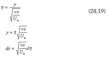
The stream function can now be obtained in terms of the velocity components as


where D is a constant. Also  and the constant of integration is zero if the stream function at the solid surface is set equal to zero.
Now, the velocity components and their derivatives are:

or

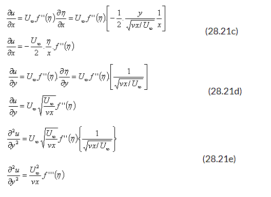
Substituting (28.2) into (28.15), we have or
or
where

and
This is known as Blasius Equation .
The boundary conditions as in Eg. (28.16), in combination with Eg. (28.21a) and (28.21b) become
 Equation (28.22) is a third order nonlinear differential equation .
- Blasius obtained the solution of this equation in the form of series expansion through analytical techniques
- We shall not discuss this technique. However, we shall discuss a numerical technique to solve the aforesaid equation which can be understood rather easily.
- Note that the equation forfdoes not containx.
- Boundary conditions at x = 0 and y = ∞ merge into the condition
 . This is the key feature of similarity solution.
 - We can rewrite Eq. (28.22) as three first order differential equations in the following way
f' = G ( 28.24a)
G = H (28.24b)(28.24c)
Let us next consider the boundary conditions.
- The condition f (0) = 0remains valid.
- The condition f' (0) = 0 means that G (0) = 0 .
- The condition f'' (∞) = 1 gives us G (∞) = 1 .
Note: that the equations for f and G have initial values. However, the value for H(0) is not known. Hence, we do not have a usual initial-value problem.
Shooting Technique
We handle this problem as an initial-value problem by choosing values of H(0) and solving by numerical methods F (n) , G (n) and H(n) .
In general, the condition G (∞) = 1. will not be satisfied for the function G arising from the numerical solution.
We then choose other initial values of H so that eventually we find an H(0) which results in G (∞) = 1 .
This method is called the shooting technique.
In Eq. (28.24), the primes refer to differentiation wrt. the similarity variable n. The integration steps following Runge-Kutta method are given below.
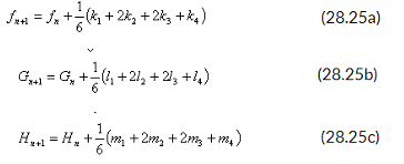
- One moves from nn +1 =nn . A fourth order accuracy is preserved if h is constant along the integration path, that is, nn +1 - n =h for all values of n . The values of k , l and m are as follows.
- For generality let the system of governing equations be
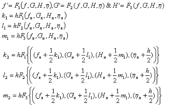
In a similar way k3 , l3, m3 and k4 , l4, m4 mare calculated following standard formulae for the Runge-Kutta integration. For example, k3 is given by  The functions F1, F2and F3 are G, H , -f/H2 respectively. Then at a distance Δn from the wall, we have

As it has been mentioned earlier F'(0) = H (0) = λ is unknown. It must be determined such that the condition F' (0) = G (∞) = 1 is satisfied.
The condition at infinity is usually approximated at a finite value of n (around n= 10 ). The process of obtaining accurately involves iteration and may be calculated using the procedure described below.
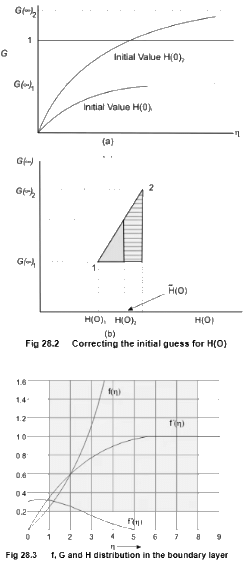
- For this purpose, consider Fig. 28.2(a) where the solutions of G versus n for two different values of H(0)are plotted.
The values of G(∞) are estimated from the G curves and are plotted in Fig. 28.2(b). - The value of
- H(0) now can be calculated by finding the value
 at which the line 1-2 crosses the line G(∞) = 1 By using similar triangles, it can be said that
  . By solving this, we get
  .
. - Next we repeat the same calculation as above by using
 and the better of the two initial values of H(0) . Thus we get another improved value
 . This process may continue, that is, we use
 and
and as a pair of values to find more improved values for H(0) , and so forth. The better guess for H (0) can also be obtained by using the Newton Raphson Method. It should be always kept in mind that for each value of H(0) , the curve G(n) versus n is to be examined to get the proper value of G(∞) .
 - The functions f(n), f' (n) = G and f" (n) =H are plotted in Fig. 28.3.The velocity components, u and v inside the boundary layer can be computed from Eqs (28.21a) and (28.21b) respectively.
- A sample computer program in FORTRAN follows in order to explain the solution procedure in greater detail. The program uses Runge Kutta integration together with the Newton Raphson method
- Measurements to test the accuracy of theoretical results were carried out by many scientists. In his experiments, J. Nikuradse, found excellent agreement with the theoretical results with respect to velocity distribution (u/ U∞) within the boundary layer of a stream of air on a flat plate.
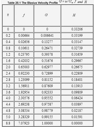
- In the next slide we'll see some values of the velocity profile shape f' (n) = (u/ U∞) = G and f" (n) = H in tabular format.
Values of the velocity profile shape f' (n) = (u/ U∞) = G and f" (n) = H
|
56 videos|154 docs|75 tests
|
FAQs on Introduction to Laminar Boundary Layers - 1 - Fluid Mechanics for Mechanical Engineering
| 1. What is a laminar boundary layer? |  |
| 2. How does the thickness of a laminar boundary layer change with distance along the surface? |  |
| 3. What is the significance of laminar boundary layers in civil engineering? |  |
| 4. How does turbulence impact laminar boundary layers? |  |
| 5. What factors affect the transition from laminar to turbulent boundary layers? |  |


