Civil Engineering (CE) Exam > Civil Engineering (CE) Notes > Geomatics Engineering (Surveying) > Levelling & Contouring
Levelling & Contouring | Geomatics Engineering (Surveying) - Civil Engineering (CE) PDF Download
Levelling
Definitions
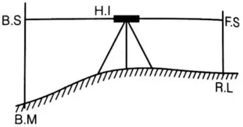
- Reduced level: The elevation of a point with respect to either Mean Sea Level (MSL) or with respect to a fixed point of known height is called reduced level.
- Bench mark: Bench mark is relatively permanent point of reference whose elevation with respect to some assumed datum is known. It is used either as a starting point for leveling or as a point upon which to close as a check.

- Back sight: After setting up the instrument Ist reading taken is called back sight. It is also known as plus sight.
- Fore sight: Last reading taken from an instrument station is called fore sight. It is also known as minus sight.
- Intermediate sight: All readings other than back sight and fore sight are intermediate sight.
- Height of instrument: It is the Reduced Level (RL) of line of sight of the instrument set up at different stations.
H.I = R.L + B.S
R.L = H.I – F.S
Arithmetic Check
- For rise and fall method
∑B.S - ∑F.S = ∑Rise - ∑Fall = Last R.L – First R.L - Height of instrument method
∑ B.S - ∑ F.S = Last R.L – First R.L
Reciprocal Levelling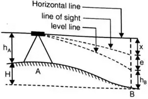 Here, X = error due to inclined line of sight, and
e = error due to curvature and refraction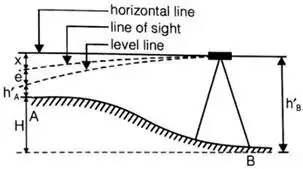
- When instrument is set up at A
Reading on staff at A = hA
Reading on staff at B = hB - When an instrument is set up at B
Reading on staff at A = h’A
Reading on staff at B = h’B
hA – hB = h’A – h’B If instrument is correct.
Here ‘H’ is the true difference of R.L between A and B. - True Readings

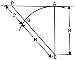
Curvature Correction (CC)
CC = -(d2/2R)
Here, d = horizontal distance between A and B
R = radius of earth
If R = 6370 km
Than CC = -0.07849d2
here ‘CC’ is in meter and ‘d’ is in kilometer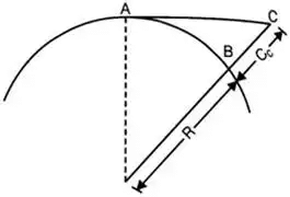
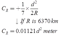
- Refraction Correction (CR)
CR = +(1/7)CC
Here d is in kilometer. - Combined Correction Due to Curvature and Refraction (C)

C = -0.06728d2 meter Here d is in kilometer. - Distance of Visible Horizon
d = 3.8553√ckm
Here ‘C’ being in meters. (taking both curvature and refraction into accounts)
Sensitiveness of Bubble Tube
Sensitiveness of the bubble tube is defined as the angular value of one division of the bubble tube.
α' = sensitivity of the bubble tube
= angular value of one division
α' = S/nD x 206265 seconds
Or α'= S/nDsin1" seconds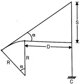
Here, S = difference between two staff readings.
n = no. of divisions of bubble
also, α' = l/R radian or α' = l/Rsin1" seconds
where, l = length of one division
R = radius of curvature of bubble tube.
Contouring
- Contours: Contour is an imaginary line joining points of equal elevation on earth surface.
- Contour interval: Vertical distance between two contour is called contour internal.
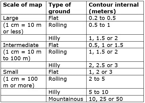
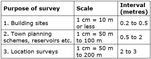
- Some suitable value of contour intervals

- Contour internal for various purposes are suggested as:

Contour interval = (25/No. of cm per km)metres
Contour interval = (50/No. of inches per mile)feet
The document Levelling & Contouring | Geomatics Engineering (Surveying) - Civil Engineering (CE) is a part of the Civil Engineering (CE) Course Geomatics Engineering (Surveying).
All you need of Civil Engineering (CE) at this link: Civil Engineering (CE)
|
19 videos|31 docs|35 tests
|
FAQs on Levelling & Contouring - Geomatics Engineering (Surveying) - Civil Engineering (CE)
| 1. What is levelling in civil engineering? |  |
Ans. Levelling in civil engineering refers to the process of determining the height or elevation of different points on the earth's surface relative to a known reference point. It is used to create accurate and detailed topographic maps, calculate volume of earthworks, and establish benchmarks for construction projects.
| 2. What are the different types of levelling techniques used in civil engineering? |  |
Ans. There are several types of levelling techniques used in civil engineering, including:
- Differential Levelling: This technique involves measuring the difference in height between two points using a leveling instrument and a leveling staff.
- Trigonometric Levelling: In this technique, the height difference between two points is determined using trigonometric calculations based on angle measurements and known distances.
- Barometric Levelling: It involves measuring the atmospheric pressure at different locations to estimate the height difference between them.
- Precise Levelling: Precise levelling uses highly accurate leveling instruments and techniques to achieve precise height measurements, typically used for critical engineering projects.
| 3. What is contouring in civil engineering? |  |
Ans. Contouring in civil engineering is the process of determining and representing contours on a topographic map. Contours are imaginary lines that connect points of equal elevation on the earth's surface. By creating contour lines, engineers can visualize the shape of the land, identify slopes, and plan drainage systems, roads, and other infrastructure.
| 4. How are contour lines represented on a topographic map? |  |
Ans. Contour lines on a topographic map are represented as continuous lines that connect points of equal elevation. They are usually labeled with the elevation value at specific intervals. Closed contour lines indicate hills or mountains, while widely spaced contour lines represent flat or gently sloping areas.
| 5. What are the applications of levelling and contouring in civil engineering? |  |
Ans. Levelling and contouring are essential for various civil engineering applications, including:
- Determining the slope and gradient of the land for designing roads, railways, and canals.
- Planning drainage systems to ensure proper water flow and prevent flooding.
- Calculating the volume of earthworks for excavation or construction projects.
- Designing foundations of structures by analyzing the stability and settlement of the ground.
- Creating accurate topographic maps for land surveying, urban planning, and environmental assessment.

|
Explore Courses for Civil Engineering (CE) exam
|

|
Signup for Free!
Signup to see your scores go up within 7 days! Learn & Practice with 1000+ FREE Notes, Videos & Tests.
Related Searches
