Machining & Machine Tool Operations - 1 | Manufacturing Engineering - Mechanical Engineering PDF Download
Introduction
A machine tool is used for holding the cutting tools which are used to remove metal from a workpiece to generate the desired product of a given size, configuration, and finish.
Classification of Machine Tool
There are many ways in which the machine tools can be classified. Here, the classification shown below is based on the production capability and application:
- General Purpose machine tools
- Production machine tools
- Special purpose machine tools
- Single purpose machine tools
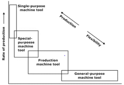 Application of machine tools based on capability
Concept of Generatrix and Directrix

The line generated by the cutting motion is called the generatrix and the line from the feed motion is termed as the directrix. Different geometries and shapes are obtained on the basis of relative directions of the generatrix and the directrix.
- Generation of various surfaces:
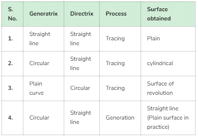
Lathe Machine and Operations
Lathe is the oldest machine tool invented, starting with the Egyptian tree lathes.
The principal form of surface produced in a lathe is the cylindrical surface. This is achieved by rotating the work piece while the single point cutting tool removes the material by traversing in a direction parallel to the axis of rotation.
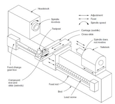 General view of a centre lathe various mechanisms and features
Types of Lathes
Considering the versatility, a large number of variants of lathes are used in manufacturing shops. The variations are:
- Centre lathe: The centre lathe is the most common of the lathes, which derives its name from the way a work piece is clamped by centres in a lathe, though this is not the only way in which the job is mounted.
Example: Bench Lathe - Tool room lathe:
(i) A tool room lathe is generally a high precision lathe having a gearbox in the headstock offering an extended range of thread pitches and feeds.
(ii) The tool room lathe is generally meant for applications of tool making, where the accuracy desired is much higher than is normally required for general production work. - Special purpose lathes: These are the form of centre lathe used for special forms of application which are difficult to made by the conventional centre lathe.
- Capstan and turret lathes
(i) These are automatic lathes which are used for high rate production and thus used for very special applications.
(ii) These have the special features to help in improving the production rate and also work unattended if necessary.
Lathe specifications
The main basic elements specified for the capability of the lathe machine are as follows:
- Distance between centres: This specifies the maximum length of the job that can be turned in the lathe.
- Swing over the bed: This specifies the maximum diameter of the job that can be turned in the lathe machine, generally restricted to small length jobs.
- Swing over the cross slide: This specifies the maximum diameter of the job that can be turned in the lathe machine with the job across the cross slide, which is generally the case.
Aids for support and location
- Chucks: The most common form of work holding device used in a lathe is the chuck.
(i) Three jaw Chuck
(a) The main advantage of this chuck is the quick way in which the typical round job is centred.
(b) The jaws will be able to centre any job, whose external locating surface is cylindrical or symmetrical, like hexagonal.
(ii) Four jaws chuck
(a) The independent jaw chuck has four jaws, which can be moved in their slots independent of each other, thus clamping any type of configuration.
(b) Since each of these jaws could move independently any irregular surface could be effectively centred. - Centers
(i) Centres would be able to locate the central axis of the work piece, however, would not be able to transmit the motion to the work piece from the spindle.
(ii) The centre located in the spindle is termed live centre while that in the tailstock is termed the dead centre.
(iii) Live centre rotates with the work piece, and hence it remains soft. Whereas the dead centre does not rotate. - Faceplate: The face plate is used for holding jobs such as thin and irregularly shaped pieces that cannot be held between the centre and chucks.
- Mandrel
(i) It is used for holding and rotating hollow workpieces or those that have been drilled or bored previously.
(ii) For holding components with locating holes, for the purpose of generating external surfaces, a mandrel is generally used.
Turning
Here, a tool having single cutting edge is used material removal from a rotating workpiece and a cylindrical shape is generated.
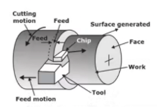 Turning operation
Taper turning
Cutting tapers on a lathe is one of the most common applications. There are various methods available for cutting tapers in a lathe. They are:
- Using a compound slide:
(i) The compound slide is an auxiliary slide underneath the tool post and above the carriage.
(ii) It is possible to swivel the compound slide to the desired angle of the tape.
(iii) The angle set on the compound slide is half the included angle of the taper required.
The empirical formula used for calculating the taper is
tan θ = (D1 - D2) / 2L
Where θ is half of the included angle, D1 and D2 are the major and minor diameters of the workpiece and L is the length of the tapered portion. - Using form tools: In this method a special form tool is sued for generating the tapers
The feed is given by plunging the tool directly into the work. Short tapers where the steepness is of no consequence, such as for chamfering, are produced by this method. - Offsetting the tailstock:
(i) By offsetting the tailstock, the axis of rotation of the job is inclined by the half angle of taper as shown in Fig.
(ii) The feed to the tool is given in the normal manner parallel to the guideways. Thus, the conical surface is generated.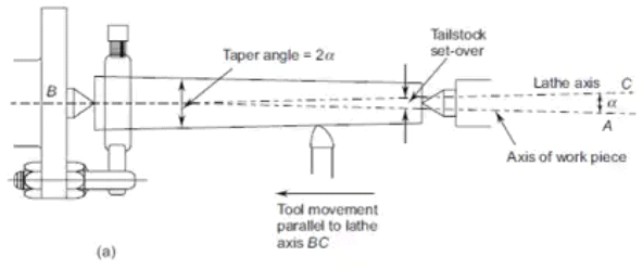
 If α is very small, then we can approximateTailstock Offset
sin α = tan α = (D - d)/2L
- Using taper turning attachment:
(i) In this method, tool is guided in a straight path at an angle to the axis of rotation of the workpiece.
(ii) The taper turning attachment is fixed on the bed lathe and the taper guide bar swivels around a pivot. The transverse feed of the carriage produces the taper.
Machining time calculation
The cutting speed in turning is the surface speed of the work piece. Thus,
V = πDn / 1000
where, V a cutting speed (surface), m/min
D = Initial diameter of the work piece, mm
N = rotational speed of the work piece, rpm
The machining{ time, t for a single pass is given by
t = L + L0 / fN
where L = length of the job, mm
L0 = over travel of the tool beyond the length of the job to help in the setting of the tool, mm
f = feed rate, mm/rev. It is the linear distance travelled for one revolution of the
workpiece along the length of the Job.
Shaper
- The shaper is a relatively slow machine tool with very low metal removal capability. Hence it is replaced by more versatile milling machine in many shops. This is a low-cost machine tool and hence is used for initial rough machining of the blanks. It is rarely used in production operations.
- It uses a single point tool similar to a lathe which is clamped to a tool post mounted to a clapper box which in turn is mounted to a reciprocating ram.
- The ram while undertaking the cutting stroke pushes the cutting tool through the work piece to remove the material. When the ram returns, no cutting takes place.
- In between the return and cutting strokes, the table moves in the horizontal direction perpendicular to the cutting direction, which is termed as the feed direction.
Machining time calculation
Let N be the rotational speed of the bull gear and L be the length of the stroke. The speed ratio indicates the proportion of time actual cutting is taking place and is defined as:
Let L: Stroke length of the ram
V = cutting velocity (or) velocity of ram during forward stroke
m = 1/Quick return ratio
Since: Vc < VT thus, Tr < Tc ⇒ m < 1
W = width of workpiece
f = feed
Tc = Time taken for cutting stroke
Tr = Time taken for return stroke
Vc = Velocity during cutting stroke
Vr = Velocity during return stroke
Time/Double Stroke (t) = L/V (l + m)
Number of strokes required: n = W/f
Total machining time:
T = t x number double strokes (n)
T = W/f x L/V(1 + m)
Planing (Planer)
- Planing machine is very similar to the shaper in terms of the Surfaces that can be generated.
- Generally, planer is used for machining large work pieces, which cannot be held in the shaper.
- In the shaper, the cutting tool reciprocates during the cutting motion, while in the case of planer the worktable reciprocates.
Planing Time Estimation:
Planing Time: 
Where I = length of the planer stroke, m
W = width of surface to be cut, mm
f = feed rate, mm/stroke
Vc = cutting speed, m/ min
Vf = table return speed, m/ min
a = time for reversal of table, min which Is about 0.015 to 0.040 minutes.
Slotting Machine (Slotter)
- Slotting machine is basically a vertical axis shaper.
- The stroke of the ram is smaller in slotting machines than in shapers to account for the type of the work that is handled in them.
Hole Making Operations
Machining round holes in metal stock is one of the most common operations in the manufacturing industry.
 Various types of holes
Drilling
- Drilling is used to create a round hole.
- It is accomplished by a rotating tool that typically has two cutting edges. The tool is fed in a direction parallel to its axis of rotation into the work part to form the round hole.
(a) Drilling Time Estimation
The cutting speed in drilling is the surface speed of the twist drill. Thus
V = πDN / 1000
Where, V = cutting speed (surface), m/min
D = diameter of the twist drill, mm
N - rotational speed of the drill, rev/min
- The initial approach (AI) is generally a small value for positioning the drill above the hole. This distance, AI can generally be taken as 2 to 3 mm.
- The traverse distance beyond the hole is often termed as the breakthrough distance and is required because of the conical shape of the twist drill.
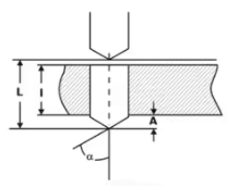 End of the twist drill showing the breakthrough distance
Break through distance, A = D / 2tanα
Time for drilling the hole = L / fN minutes
Where f = feed rate, mm/rev
Material removal rate
MRR = πD2fN / 4
|
56 videos|80 docs|29 tests
|
FAQs on Machining & Machine Tool Operations - 1 - Manufacturing Engineering - Mechanical Engineering
| 1. What is machining and why is it important in mechanical engineering? |  |
| 2. What are the different types of machining operations? |  |
| 3. What factors should be considered when selecting the appropriate machining process for a specific application? |  |
| 4. What are the advantages and disadvantages of CNC machining? |  |
| 5. How can the efficiency of machining operations be improved? |  |


