Maximum Power Transfer Theorem | Network Theory (Electric Circuits) - Electrical Engineering (EE) PDF Download
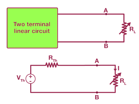
The Maximum Power Transfer Theorem is not primarily a tool for circuit analysis; rather, it is a crucial concept for optimizing system design. The theorem states that the maximum power is delivered to a load when the load resistance (or impedance in AC circuits) is equal to the Thevenin or Norton equivalent resistance (or impedance) of the source network. If the load resistance deviates from this value, the power dissipated by the load will be less than the maximum possible.:

- Thevenin/Norton Equivalent Resistance:
- For maximum power transfer in a circuit, the load resistance (RL) must be equal to the Thevenin resistance (Rth) of the source. In AC circuits, the load impedance (ZL) should match the source impedance (Zth).
- Power Dissipation:
- When RL=Rth, the power transferred to the load is at its peak.
- If RL is greater or less than Rth, the power dissipated in the load decreases.
- Applications in Radio Transmitter Design:
- In designing radio transmitters, it is crucial to match the impedance of the antenna or transmission line to the impedance of the final power amplifier. This matching ensures maximum RF power output.
- Impedance Matching: Impedance is the total opposition a circuit presents to alternating and direct currents. For optimal power transfer, the source and load impedances must be equal.
- Effects of Impedance Mismatch:
- If the load impedance (ZL) is too high, the power output decreases significantly.
- If the load impedance (ZL) is too low, not only does the power output decrease, but there is also a risk of overheating the amplifier. This overheating occurs because excessive power is dissipated within the source's internal impedance.
Mathematical Formulation:
- For DC Circuits:
 is the Thevenin equivalent voltage, and Rth is the Thevenin equivalent resistance.
 - For AC Circuits:
 is the Thevenin equivalent voltage, and RthR_{th}Rth is the resistive part of the Thevenin equivalent impedance.
Practical Implications
- System Design:
- Ensuring that the load matches the source impedance is crucial in various applications, especially in communications and signal transmission systems.
- Efficiency:
- Proper impedance matching leads to efficient energy transfer, reducing losses and improving overall system performance.
- Component Protection:
- Correct matching prevents components like amplifiers from overheating, thus extending their operational life and reliability.
Maximum Power Transfer Example
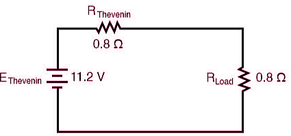
Taking our Thevenin equivalent example circuit, the Maximum Power Transfer Theorem tells us that the load resistance resulting in greatest power dissipation is equal in value to the Thevenin resistance (in this case, 0.8 Ω):

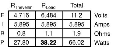
With this value of load resistance, the dissipated power will be 39.2 watts:
If we were to try a lower value for the load resistance (0.5 Ω instead of 0.8 Ω, for example), our power dissipated by the load resistance would decrease:
Power dissipation increased for both the Thevenin resistance and the total circuit, but it decreased for the load resistor. Likewise, if we increase the load resistance (1.1 Ω instead of 0.8 Ω, for example), power dissipation will also be less than it was at 0.8 Ω exactly:

If you were designing a circuit for maximum power dissipation at the load resistance, this theorem would be very useful. Having reduced a network down to a Thevenin voltage and resistance (or Norton current and resistance), you simply set the load resistance equal to that Thevenin or Norton equivalent (or vice versa) to ensure maximum power dissipation at the load. Practical applications of this might include radio transmitter final amplifier stage design (seeking to maximize the power delivered to the antenna or transmission line), a grid-tied inverter loading a solar array, or electric vehicle design (seeking to maximize the power delivered to drive motor).
Maximum Power Doesn't Equate to Maximum Efficiency
The Maximum Power Transfer Theorem is often misunderstood to imply maximum efficiency, which it does not. In AC power distribution systems, achieving maximum power transfer does not lead to high efficiency. High efficiency requires a low generator impedance relative to the load impedance.
Key Concepts:
- AC Power Distribution: To achieve high efficiency, the generator's impedance should be much lower than the load's impedance.
- High-Fidelity Audio Amplifiers: These amplifiers are designed with a low output impedance and a high speaker load impedance to maintain sound quality. The ratio of output impedance to load impedance is called the damping factor, typically ranging from 100 to 1000.
- Noise Reduction: In radio frequency amplifiers, minimizing noise often involves mismatching the input impedance of the amplifier to the antenna, contrary to the maximum power transfer theorem.
Review:
- The Maximum Power Transfer Theorem states that maximum power is dissipated in the load when the load resistance equals the Thevenin or Norton resistance of the source.
- This theorem does not align with achieving maximum efficiency or minimal noise in practical applications.
Example for Better Understanding
Consider a power distribution system with a generator impedance of 1 Ω and a load impedance of 100 Ω. For maximum efficiency, the generator impedance should be much lower than the load impedance, contrary to the conditions for maximum power transfer.
|
68 videos|85 docs|62 tests
|

|
Explore Courses for Electrical Engineering (EE) exam
|

|
 is the Thevenin equivalent voltage, and Rth is the Thevenin equivalent resistance.
 is the Thevenin equivalent voltage, and RthR_{th}Rth is the resistive part of the Thevenin equivalent impedance.


