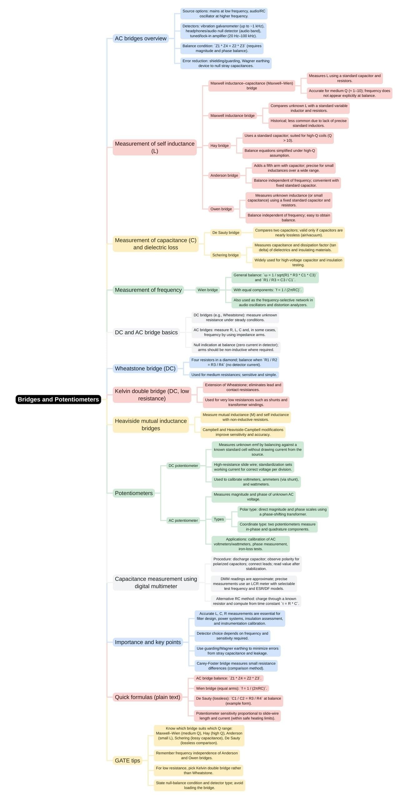
Electrical Engineering (EE) Exam > Electrical Engineering (EE) Notes > Electrical and Electronic Measurements > Mind Map: Bridges and Potentiometers
Mind Map: Bridges and Potentiometers | Electrical and Electronic Measurements - Electrical Engineering (EE) PDF Download

The document Mind Map: Bridges and Potentiometers | Electrical and Electronic Measurements - Electrical Engineering (EE) is a part of the Electrical Engineering (EE) Course Electrical and Electronic Measurements.
All you need of Electrical Engineering (EE) at this link: Electrical Engineering (EE)
|
48 videos|57 docs|22 tests
|
FAQs on Mind Map: Bridges and Potentiometers - Electrical and Electronic Measurements - Electrical Engineering (EE)
| 1. What is the function of a bridge circuit in electrical engineering? |  |
Ans.A bridge circuit is used to measure unknown electrical resistances by balancing two legs of a bridge circuit. The most common type is the Wheatstone bridge, which allows for precise measurements by comparing the unknown resistance to known resistances.
| 2. How do potentiometers work and what are their applications? |  |
Ans.Potentiometers are three-terminal resistive devices that can vary their resistance based on the position of a movable contact. They are commonly used as variable resistors in applications like volume controls, position sensors, and as voltage dividers in circuits.
| 3. What are the key differences between series and parallel configurations in bridge circuits? |  |
Ans.In series configurations, the total resistance is the sum of individual resistances, while in parallel configurations, the total resistance is less than the smallest individual resistance. This affects how voltage and current are distributed in the circuit, which is crucial for accurate measurements in bridge applications.
| 4. What is the significance of the null point in a potentiometer? |  |
Ans.The null point in a potentiometer is the point at which the voltage across the potentiometer is zero, indicating that the circuit is balanced. This is significant as it allows for the accurate determination of unknown voltages or resistances without drawing current from the circuit being measured.
| 5. Can bridge circuits be used for AC measurements, and if so, how? |  |
Ans.Yes, bridge circuits can be adapted for AC measurements using components like capacitors and inductors, forming AC bridges such as the Maxwell bridge and Schering bridge. These circuits allow for the measurement of impedance, capacitance, and inductance in AC systems, providing essential data for various electrical engineering applications.
Related Searches


