Negative Feedback Systems | Control Systems - Electrical Engineering (EE) PDF Download
Introduction
- Feedback is the process by which a fraction of the output signal, either a voltage or a current, is used as an input. If this feed back fraction is opposite in value or phase (“anti-phase”) to the input signal, then the feedback is said to be Negative Feedback, or degenerative feedback.
- Negative feedback opposes or subtracts from the input signals giving it many advantages in the design and stabilisation of control systems. For example, if the systems output changes for any reason, then negative feedback affects the input in such a way as to counteract the change.
- Feedback reduces the overall gain of a system with the degree of reduction being related to the systems open-loop gain. Negative feedback also has effects of reducing distortion, noise, sensitivity to external changes as well as improving system bandwidth and input and output impedances.
- Feedback in an electronic system, whether negative or positive feedback is unilateral in direction. Meaning that its signals flow one way only from the output to the input of the system. This then makes the loop gain, G of the system independent of the load and source impedances.
- As feedback implies a closed-loop system it must therefore have a summing point. In a negative feedback system this summing point or junction at its input subtracts the feedback signal from the input signal to form an error signal, β which drives the system. If the system has a positive gain, the feedback signal must be subtracted from the input signal in order for the feedback to be negative as shown.
Negative Feedback Circuit
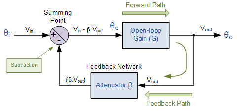
- The circuit represents a system with positive gain, G and feedback, β. The summing junction at its input subtracts the feedback signal from the input signal to form the error signal Vin – βG, which drives the system.
- Then using the basic closed-loop circuit above we can derive the general feedback equation as being:
Negative Feedback Equation
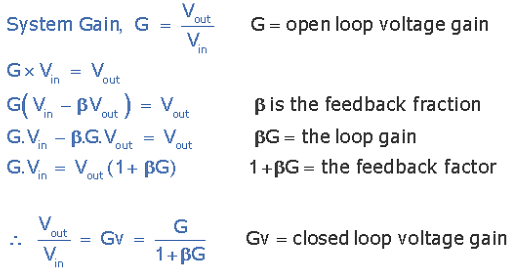
- We see that the effect of the negative feedback is to reduce the gain by the factor of: 1 + βG. This factor is called the “feedback factor” or “amount of feedback” and is often specified in decibels (dB) by the relationship of 20 log (1+ βG).
Effects of Negative Feedback
- If the open-loop gain, G is very large, then βG will be much greater than 1, so that the overall gain of the system is roughly equal to 1/β. If the open-loop gain decreases due to frequency or the effects of system ageing, providing that βG is still relatively large, the overall system gain does not change very much. So negative feedback tends to reduce the effects of gain change giving what is generally called “gain stability”.
Negative Feedback in Operational Amplifiers
- Operational amplifiers (op-amps) are the most commonly used type of linear integrated circuit but they have a very high gain. The open-loop voltage gain, AVOL, of a standard 741 op-amp is its voltage gain when there is no negative feedback applied and the open-loop voltage gain of an op-amp is the ratio of its output voltage, Vout, to its differential input voltage, Vin, ( Vout/Vin ).
- The typical value of AVOL for a 741 op-amp is more than 200,000 (106dB). So an input voltage signal of only 1mV, would result in an output voltage of over 200 volts! forcing the output immediately into saturation. Obviously this high open-loop voltage gain needs to be controlled in some way, and we can do just that by using negative feedback.
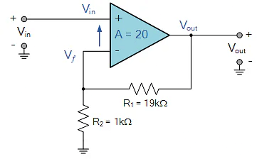
- The use of feedback can significantly improve the performance of an operational amplifier and any op-amp circuit that does not use feedback is considered too unstable to be useful. But how can we use negative feedback to control an op-amp. Well consider the circuit below of a Non-inverting Operational Amplifier.
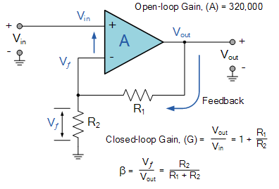
Non-inverting Op-amp Circuit
- There are many advantages to using feedback within a systems design, but the main advantages of using Negative Feedback in amplifier circuits is to greatly improve their stability, better tolerance to component variations, stabilisation against DC drift as well as increasing the amplifiers bandwidth.
- Examples of negative feedback in common amplifier circuits include the resistor Rƒ in op-amp circuits as we have seen above, resistor, RS in FET based amplifiers and resistor, RE in bipolar transistor (BJT) amplifiers.
Example Negative Feedback Systems
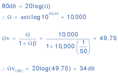
Example 1. A system has a gain of 80dB without feedback. If the negative feedback fraction is 1/50th. Calculate the closed-loop gain of the system in dB with the addition of negative feedback.
Then we can see that the system has a loop gain of 10,000 and a closed-loop gain of 34dB.
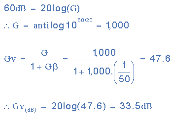
Example 2. If after 5 years the loop gain of the system without negative feedback has fallen to 60dB and the feedback fraction has remained constant at 1/50th. Calculate the new closed-loop gain value of the system.
Then we can see from the two examples that without feedback, after 5 years of use the systems gain has fallen from 80dB down to 60dB, (10,000 to 1,000) a drop in open loop gain of about 25%. However with the addition of negative feedback the systems gain has only fallen from 34dB to 33.5dB, a reduction of less than 1.5%, which proves that negative feedback gives added stability to a systems gain. Therefore we can see that by applying negative feedback to a system greatly reduces its overall gain compared to its gain without feedback. The systems gain without feedback can be very large but not precise as it may change from one system device to the next, then it is possible to design a system with sufficient open-loop gain that, after the negative feedback has been added, the overall gain matches the desired value.Also, if the feedback network is constructed from passive elements having stable characteristics, the overall gain becomes very steady and unaffected by variation in the systems inherent open-loop gain.
Example 3. An operational amplifier with an open-loop voltage gain, AVOL of 320,000 without feedback is to be used as a non-inverting amplifier. Calculate the values of the feedback resistances, R1 and R2 required to stabilise the circuit with a closed loop gain of 20.
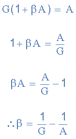
The generalised closed-loop feedback equation we derived above is given as:
By rearranging the feedback formula we get a feedback fraction, β of:
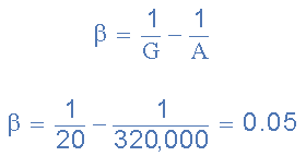
Then putting the values of: A = 320,000 and G = 20, into the above equation we get the value of β as:
Because in this case the open-loop gain of the op-amp is very high ( A = 320,000 ), the feedback fraction, β will be roughly equal to the reciprocal of the closed-loop gain 1/G only as the value of 1/A will be incredibly small. Then β (the feedback fraction) is equal to 1/20 = 0.05.
As the resistors, R1 and R2 form a simple series-voltage potential divider network across the non-inverting amplifier, the closed-loop voltage gain of the circuit will be determined by the ratios of these resistances as:
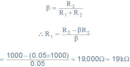
If we assume resistor R2 has a value of 1,000Ω, or 1kΩ, then the value of resistor R1 will be:
Then for the non-inverting amplifier circuit about to have a closed-loop gain of 20, the values of the negative feedback resistors required will be in this case, R1 = 19kΩ and R2 = 1kΩ, giving us a non-inverting amplifier circuit of:Non-inverting Op-amp Circuit
- There are many advantages to using feedback within a systems design, but the main advantages of using Negative Feedback in amplifier circuits is to greatly improve their stability, better tolerance to component variations, stabilisation against DC drift as well as increasing the amplifiers bandwidth.
- Examples of negative feedback in common amplifier circuits include the resistor Rƒ in op-amp circuits as we have seen above, resistor, RS in FET based amplifiers and resistor, RE in bipolar transistor (BJT) amplifiers.
|
53 videos|115 docs|40 tests
|

