The fundamental theories on which many branches of electrical engineering, such as Power Systems, Electric Machines, Control Systems, Analog Electronics, and Instrumentation are built on Network theorems.
Network theorems are crucial elements of Network Theory because they provide essential tools for simplifying and analyzing complex Electrical Networks.
Note:
All the theorems are only applicable to Linear Networks only, according to the theory of Linear Network they follow the condition of Homogeneity & Additivity.
So, before jumping to the theorems let's first understand the conditions for Linear Networks.
Linear Networks
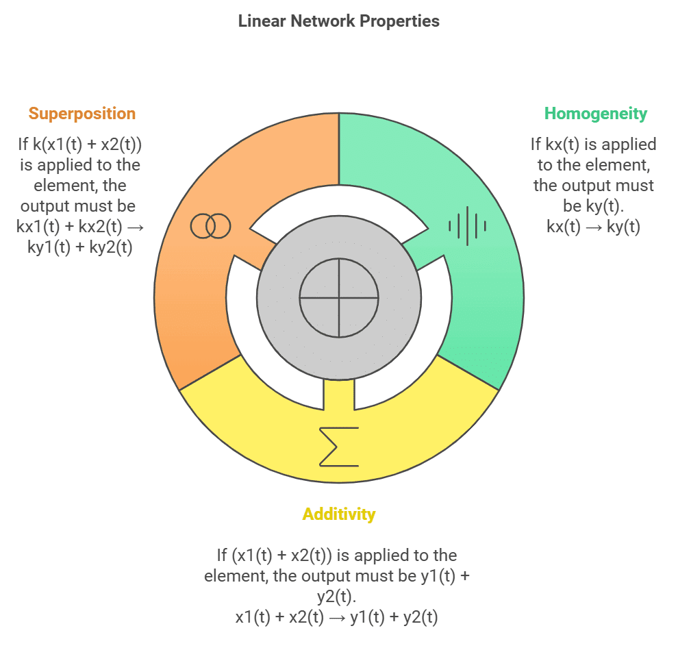
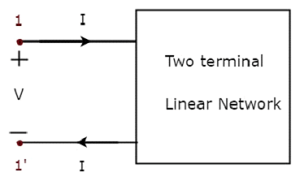
An element is considered linear if it satisfies the homogeneity (scaling) property and additive (superposition) property.
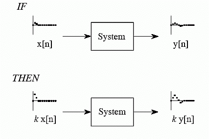
1. Homogeneity Property
Let x be the input and y be the output of an element.
x(t) → y(t)
If kx(t) is applied to the element, the output must be ky(t).
kx(t) → ky(t)
Homogeneity Property
2. Additivity Property
x1(t) → y1(t), x2(t) → y2(t)
If (x1(t) + x2(t)) is applied to the element, the output must be y1(t) + y2(t).
x1(t) + x2(t) → y1(t)+ y2(t)
Superposition Property
If k(x1(t) + x2(t)) is applied to the element, the output must be k(y1(t) + y2(t)).
kx1(t) + kx2(t) → ky1(t) + ky2(t)
So, for a network to qualify the application of various theorems must follow the conditions given above.
Superposition Theorem
It states that in a linear network with a number of independent sources, the response can be found by summing the responses to each independent source acting alone, with all other independent sources set to zero.
Procedure for using the superposition theorem
Step-1: Retain one source at a time in the circuit and replace all other sources with their internal resistances.
Step-2: Determine the output (current or voltage) due to the single source acting alone.
Step-3: Repeat steps 1 and 2 for each of the other independent sources.
Step-4: Find the total contribution by adding algebraically all the contributions due to the independent sources.
So for above given circuit the total response or say current I through resistor R2 will be equal to the sum of individual response obtained by each source.
I' ⇨ due to source E1 alone
I'' ⇨ due to source E2 alone
I''' ⇨ due to source Ix alone
current through resistor R2 ⇨I = I'+ I''+ I'''
Question for Network Theorems - 1
Try yourself: In superposition theorem, when we consider the effect of one voltage source, all the other voltage sources are ____________.
Explanation
In superposition theorem when we consider the effect of one voltage source, all the other voltage sources are shorted and current sources are opened.
Report a problem
View Solution
Removing of Active Element in Superposition Theorem
Limitation of Superposition Theorem
Superposition cannot be applied to power effects because the power is related to the square of the voltage across a resistor or the current through a resistor.
Example:
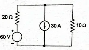
Here in the following electrical circuit, we will find the current flowing through the 10 Ω resistor using the superposition theorem.
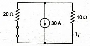
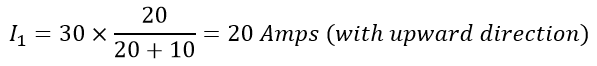
Solution: Here at first let’s consider the 30 A current source. So we will leave the 30 A current source as it is in the circuit and replace the 60 V voltage source with the short circuit as shown below.
Now the current through 10 Ω resistor is calculated as
[The I1 is calculated using the current divider.]
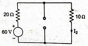
Now let’s consider a 60 V voltage source. So we will leave the 60 V voltage source as it is and replace the 30 A current source with the open circuits shown below.
Then current through 10 Ω resistor is calculated as
Finally, the total current flowing through the 10 Ω resistor is the algebraic sum of I1 and I2.
Thevenin's Theorem
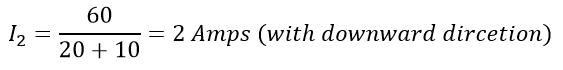
Thevenin’s theorem states that any two output terminals of an active linear network containing independent sources (it includes voltage and current sources) can be replaced by a simple voltage source of magnitude VTHin series with a single resistor RTH
where.
RTH is the equivalent resistance of the network when looking from the output terminals A & B with all sources (voltage and current) removed and replaced by their internal resistances
VTH is equal to the open circuit voltage across the A & B terminals.
Thevenin Circuit
Procedure for applying Thevenin’s theorem
Open the load resistor.
Calculate/measure the open circuit voltage. This is the Thevenin Voltage (VTH).
Open current sources and short voltage sources.
Calculate /measure the Open Circuit Resistance. This is the Thevenin Resistance (RTH).
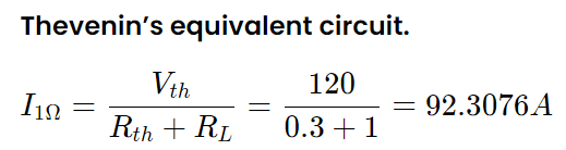
Now, redraw the circuit with measured open circuit Voltage (VTH) in Step (2) as a voltage source and measured open circuit resistance (RTH) in Step (4) as series resistance and connect the load resistor which we had removed in Step (1). This is the equivalent Thevenin circuit of that linear electric network or complex circuit which had to be simplified and analyzed by Thevenin’s Theorem.
Now find the Total current flowing through the load resistor by using Ohm’s Law: IT = VTH / (RTH + RL).
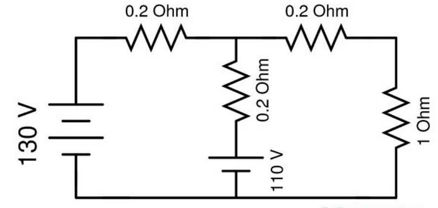
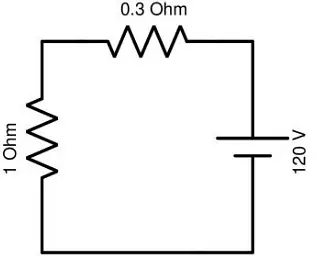
Example: Find current flowing through 1 \OmegaΩ resistor.
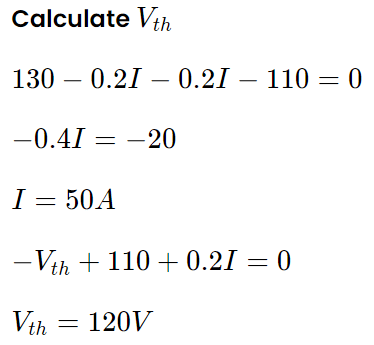
Solution: Open Load Resistor
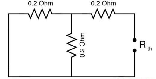
Voltage Source are shorted
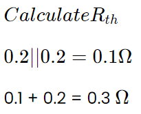
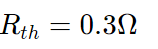
Equivalent Circuit to find Rth
Let us solve a Previous Year's Question that appeared in GATE EE 2020.
Question:
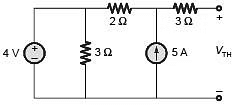
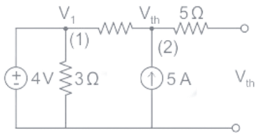
The Thevenin equivalent voltage, VTH, in V (rounded off to 2 decimal places) of the network shown below, is _______ . [GATE EE 2020]
Solution:
From the figure we can observe that,
V1 = 4V
As the load is open, therefore the current flowing through 5 Ohm resistor is zero.
By applying the nodal analysis, we get
Therefore, Vth = 14 V
Question for Network Theorems - 1
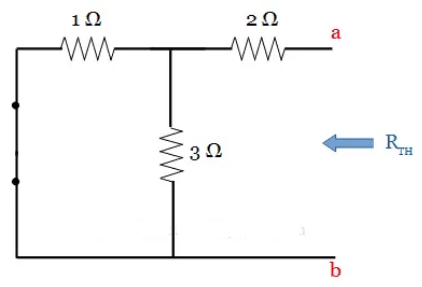
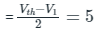
Try yourself:Calculate the Thevenin resistance and Thevenin voltage across the terminal AB for the following circuit.
Explanation
Thevenin resistance is found by opening the circuit between the specified terminal and shorting all voltage sources.
When the 10V source is shorted, we get:
Rth=(1||2)+3=3.67 ohm.
Now to calculate Thevenin voltage across AB.
4 ohm is removed and then v across 2 ohm is calculated by voltage divider 2*10/(2+1) = 6.67V.
Voltage between A and B i.e. Vth is equal to voltage across 4 ohm resistance since no current flow through 3 ohm resistance.
So, Vth = 6.67V.
Report a problem
View Solution
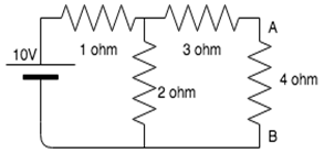
Norton's Theorem
Norton’s theorem states that any linear network containing can be replaced by a current source and a parallel resistor.
RN = RTHis the equivalent resistance of the network when looking from the output terminals A & B with all sources (voltage and current) removed and replaced by their internal resistances and the magnitude of VTH is equal to the open circuit voltage across the A & B terminals.
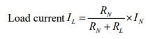
IN is the Load current.
Norton's Circuit
Example:
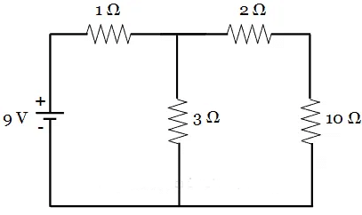
For the given circuit, determine the current flowing through 10 Ω resistor using Norton’s theorem.
Since the question here, is to determine the current through 10 Ω resistor, it is considered as the load.
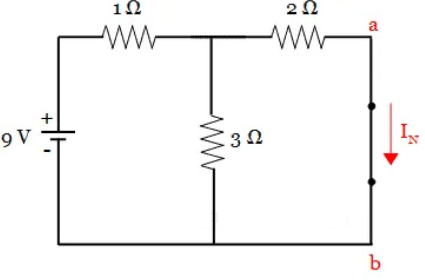
(a) To find Norton’s current, Remove the load resistor(10 Ω), short it with a wire and the circuit is redrawn as below.
In this circuit, we need to find the current IN, which is Norton’s current flowing from a to b. To find the value of IN, it is necessary to determine the total current in the circuit.
If you observe the circuit, 3 Ω resistor and 2 Ω resistor are in parallel with each other. This parallel combination is in series with 1 Ω resistor. Thus,
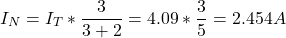
Now, the total current IT is given by,
The current through the 2 Ω resistor (or Norton’s current IN) is obtained by applying current division rule:
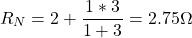
(b) To find Norton’s resistance, remove the load resistor, short the voltage source and circuit is redrawn as below.
In this circuit, we can observe that the 2 Ω resistor is in series with the parallel combination of 1 Ω and 3 Ω resistors. Thus the equivalent value of resistance is obtained as,
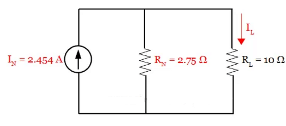
(c) Norton’s Equivalent Circuit. It is drawn by connecting Norton’s voltage IN, Norton’s resistance RN and load resistor in series, as shown below:
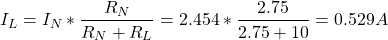
From this circuit, the current through the load RL = 10 Ω resistor is obtained using current division rule. It is given by,
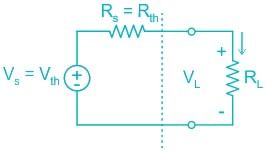
Maximum Power Transfer Theorem
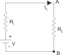
The maximum power transfer theorem states that, to obtain maximum external power from a source with a finite Internal Impedance (Say Resistance) the resistance of the load must equal to the resistance of the source as viewed from its output terminals.
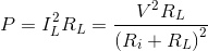
Power delivered to the load resistance:
To find the maximum power, differentiate the above expression with respect to resistance RL and equate it to zero. Thus, Thus in this case, the maximum power will be transferred to the load when load resistance is just equal to internal resistance of the battery.
Results of Maximum Power Transfer Theorem
The maximum power transfer takes place when the load resistance RL = Rth
The maximum power transferred to the load Pmax = PL (RL = Rth) = (Vth)2/ 4Rth
The efficiency of power transfer η = PL/Ps
where PL- Power delivered to the Load
Ps- Power Generated by Source
Note: Maximum power transfer condition results in 50 percent efficiency in Thevenin equivalent, however much lower efficiency in the original circuit.
Example:
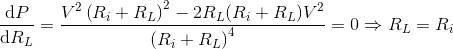
The maximum power drawn by the load RL in the below circuit will be:
Calculation:
Here Rth= 5 ohm and Vth= 10 V and RL= 5 ohm.
So Thevenin equivalent would be:
So, power across load can be calculated by calculating current I across RL.
I = Vth/Req
Req = 5 + 5
= 10 ohm
I = 10/10
I = 1 A.
So, power across RL = I2RL
= 1 × 5
= 5 W
Frequently Asked Questions (FAQs)
Q.1. What is the superposition theorem?
Superposition theorem is a circuit analysis theorem that is used to solve the network where two or more sources are present and connected.
Q.2. Is the superposition theorem valid for AC circuits?
The superposition theorem is valid for AC circuits.
Q.3. Is the superposition theorem applicable to power?
The requisite of linearity indicates that the superposition theorem is only applicable to determine voltage and current, but not power. Power dissipation is a nonlinear function that does not algebraically add to an accurate total when only one source is considered at a time.
Q.4. Can the superposition theorem be applied to non-linear circuits?
No, the superposition theorem can only be applied to non-linear circuits.
Q.5. Why do we use the superposition theorem?
The superposition theorem is very important in circuit analysis because it converts a complex circuit into a Norton or Thevenin equivalent circuit.
FAQs on Network Theorems - 1 - Network Theory (Electric Circuits) - Electrical Engineering (EE)
1. What is the Superposition Theorem and how is it applied in linear circuits?
Ans. The Superposition Theorem states that in a linear circuit with multiple independent sources, the total current or voltage at any point in the circuit is equal to the algebraic sum of the currents or voltages caused by each independent source acting alone, while all other independent sources are turned off (voltage sources are replaced with short circuits and current sources with open circuits). It is applied by analyzing the circuit multiple times, once for each independent source, and then summing the results.
2. How does Thevenin's Theorem simplify complex circuits for analysis?
Ans. Thevenin's Theorem simplifies complex linear circuits into a simple equivalent circuit consisting of a single voltage source (Thevenin voltage) in series with a single resistor (Thevenin resistance). To apply this theorem, you first remove the load resistance from the circuit, calculate the open-circuit voltage across the terminals (Thevenin voltage), and then find the equivalent resistance seen from the terminals after deactivating all independent sources. This simplification makes analyzing the circuit with different load conditions much easier.
3. What is Norton's Theorem and how is it related to Thevenin's Theorem?
Ans. Norton's Theorem states that any linear circuit with multiple sources can be replaced by an equivalent current source (Norton current) in parallel with a single resistor (Norton resistance). It is directly related to Thevenin's Theorem, as both theorems provide equivalent circuit representations; specifically, the Norton current can be found as the short-circuit current through the load terminals, and the Norton resistance is the same as the Thevenin resistance. Both methods can be used interchangeably to analyze circuits.
4. What is the Maximum Power Transfer Theorem in the context of circuit design?
Ans. The Maximum Power Transfer Theorem states that maximum power is delivered to a load when the load resistance is equal to the Thevenin resistance of the source network (i.e., R_load = R_thevenin). This theorem is crucial in circuit design, particularly in communication systems and power delivery, as it helps engineers optimize the efficiency of power transfer between different circuit components.
5. How can the concepts of these network theorems be utilized in practical engineering applications?
Ans. The concepts of network theorems such as Superposition, Thevenin's, Norton's, and Maximum Power Transfer are widely used in practical engineering applications for circuit design, analysis, and troubleshooting. These theorems allow engineers to simplify complex circuits, predict circuit behavior under various conditions, optimize power transfer and efficiency, and facilitate the design of reliable electronic devices. Understanding and applying these theorems can lead to better performance and lower costs in circuit-related projects.

 Homogeneity Property
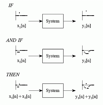 Superposition Property
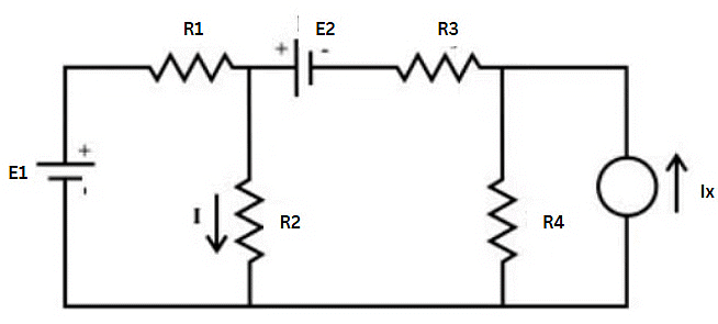

 Thevenin Circuit
Solution: Open Load Resistor
Equivalent Circuit to find Rth
 Norton's Circuit