Numerical Problems - Working Stress Method - Civil Engineering (CE) PDF Download

Instructional Objectives: At the end of this lesson, the student should be able to:
- employ the equations established for the analysis and design of singly and doubly-reinforced rectangular beams,
- use tables of SP-16 for the analysis and design of singly and doublyreinforced rectangular beams,
- understand the economy in the design by limit state of collapse.
13.35.1 Introduction
The equations for the analysis and design of singly and doubly-reinforced rectangular beams. The applications of the equations are illustrated in this lesson through the solutions of several numerical problems. Direct computation method and use of tables of SP-16 are the two approaches for the analysis and design of singly and doubly-reinforced rectangular beams. In direct computation method, the derived equations are employed directly, while the use of tables of SP-16 gives the results quickly with several alternatives avoiding tedious calculations. Some of the numerical problems are solved using both methods. Problems having the same width and effective depth but of different grades of steel are solved to compare the results. Moreover, problems of singly and doubly-reinforced rectangular beams, solved earlier by limit state of collapse method are also taken up here to compare the results. It is shown that the beams designed by limit state of collapse method are economical. In addition to illustrative examples, practice and test problems are also given in this lesson. Understanding the solved numerical examples and solving the practice and test problems will help in following the applications of the equations and the use of tables of SP-16 in analysing and designing singly and doubly-reinforced rectangular beams.
13.35.2 Numerical Problems
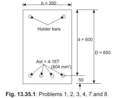
Problem 1. (a) Determine the moment of resistance of the rectangular beam of Fig. 13.35.1 having b = 350 mm, d = 600 mm, D = 650 mm, Ast = 804 mm2 (4-16T), σcbc = 7 N/mm2 and σst = 230 N/mm2.
(b) Determine the balanced moment of resistance of the beam and the balanced area of tension steel.
(c) Determine the actual compressive stress of concrete fcbc and tensile stress of steel fst when 60 kNm is applied on the beam. Use direct computation method for all three parts.
Solution 1. 1 (a): Given data are: b = 350 mm, d = 600 mm, Ast = 804 mm2, σ cbc = 7 N/mm2 and σst = 230 N/mm2.
We have: pt = Ast (100) / bd = 80400 / (350) (600) = 0.383 per cent and m = 93.33 /σcbc = 93.33 /7 = 13.33. We determine the value of k from Eq. 13.16.
k = - (pt m /100) + {(pt m/100)2 + (pt m/50)}1/2 (13.16)
= - 0.051 + 0.323 = 0.272
j = 1- k/3 = 0.909
Equation 13.17 gives the moment of resistance of the beam as,
M = (pt/100) σst (1 – k/3) bd2 (13.17)
= (0.383/100) (230) (0.909) (350) (600) (600) = 100.89 kNm.
1 (b): The balanced moment of resistances and pt, bal of the beam is obtained from Eqs. 13.10, 13.11 and 13.13. Mb = Rbbd2 (13.10)
Rb = (1/2) σ cbc kb jb = (pt, bal /100) σ st jb (13.11)
pt, bal = 50 kb (σ cbc /σ st ) (13.13)
where kb = 93.33 /(σ st + 93.3 3 ) (13.3) jb = 1- kb /3 (13.12)
The values of Rb and pt, bal may also be taken from Tables 13.3 and 13.4, respectively of Lesson 34.
Here, kb = 93.33 / (230 + 93.33) = 0.288 and jb = 1- 0.288/3 = 0.904. pt, bal = 50 kb (σ cbc /σ st) = 50 (0.288) (7/230) = 0.438 pt, bal is 0.44 from Table 13.4.
Therefore, Mb = (1/2)σ cbc kb jb (bd2) = 114.81 kNm, and
Mb = (pt, bal /100) σ st jb (bd2) = 114.75 kNm
Taking Rb from Table 13.3, we get:
Mb = Rb (bd2) = 0.91 (350) (600)2 = 114.66 kNm
The balanced area of steel = pt,bal (bd /100) = 0.438 (350) (600) /100 = 919.8 mm2.
The beam has 4-16 mm diameter bars having 804 mm2.
So, additional amount of steel = 919.8 – 804 = 115.8 mm2 is needed to make the beam balanced.
1`(c): The actual stresses in steel and concrete fst and fcbc are obtained from Eqs. 13.24 and 13.25, respectively.
fst = M /{Ast d (1- k/3)} (13.24)
fcbc = (2 Ast fst) / ( b k d) (13.25)
where Ast = 804 mm2 and k = 0.272 (obtained in part a of the solution of this problem). Thus, we have:
fst = 60000000 / 804 (600) (0.909) = 136.83 N/mm2 〈 230 N/mm2
fcbc = 2(804) (136.83) / (350) (0.272) (600) = 3.85 N/mm2 〈 7 N/mm2
Problem 2. Solve part a of Problem 1 (Fig. 13.35.1) by employing table of SP16.
Solution 2.
Given data are: pt = 0.383 per cent, σcbc = 7 N/mm2 and σst = 230 N/mm2.
Table 69 of SP-16 gives R = 0.7956 (by linear interpolation). Accordingly, the moment of resistance of the beam is M = R bd2 = (0.7956) (350) (600) (600) = 100.246 kNm.
The moment of resistance of the beam is 100.89 kNm by direct computation, as obtained in part a of Problem 1.
Problem 3. Solve Problem 1 (Fig. 13.35.1) when σcbc = 7 N/mm2 and σst = 140 N/mm2 (mild steel) for all three parts. For part c, the applied moment is 40 kNm. Other values/data remain unchanged.
Solution 3. 3 (a): Given data are: b = 350 mm, d = 600 mm, Ast= 804 mm2, σcbc 7 N/mm2 and σst = 140 N/mm2. We have from
Problem 1: pt = 0.383 per cent, m = 13.33, k = 0.272, and j = 0.909. From Eq. 13.17, we get: M = (pt / 100) σst (1 – k/3) bd2 (13.17)
= (0.383 / 100) (140) (0.909) (350) (600) (600) = 61.41 kNm 3 (b):
Here kb = 93.33 / (140 + 93.33) = 0.4; jb = 0.87, pt,bal = 50 kb (σcbc /σst) = 50 (0.4) (7/140) = 1.0 (Table 13.4 also gives pt,bal = 1).
Therefore, Mb = (1/2) σ cbc kb jb (bd2) (13.10)
= (1/2) (7) (0.4) (0.87) (350) (600) (600) = 153.47 kNm Mb = (pt, bal/100) σ st (jb) (bd2) (13.11)
= (1/100) (140) (0.87) (350) (600) (600) = 153.47 kNm
and, taking Rb from Table 13.3, we have from Eq. 13.10, Mb = R bd2 = (1.21) (350) (600) (600) = 152.46 kNm.
The balanced area of steel is obtained from taking pt, bal from Table 13.4. Accordingly, we get balanced area of steel = 1 (350) (600)/100 = 2100 mm2.
The beam is having 4-16 mm diameter bars of area 804 mm2.
The additional area of steel = 1296 mm2 is needed to make the beam balanced.
3.(c): fst = M / {Ast d (1- k/3)} (13.24)
This gives fst = 40000000 / (804) (600) (0.909) = 91.22 N/mm2 〈 140 N/mm2 fcbc = (2 Ast fst) / b kd (13.25)
So, fcbc = 2 (804) (91.22) / (350) (0.272) (600) = 2.57 N/mm2 〈 7 N/mm2
Problem 4. Solve part a of Problem 3 (Fig. 13.35.1) by using table of SP-16.
Solution 4.
Given data are: pt = 0.383 per cent, σcbc = 7 N/mm2 and σst = 140 N/mm2.
Table 69 of SP-16 gives R = 0.48436 (by linear interpolation). Accordingly, the moment of resistance of the beam is
M = R b d2 = (0.48436) (350) (600) (600) = 61.03 kNm.
The moment of resistance of this beam is 61.41 kNm by direct computation, as obtained in part a of Problem 3.
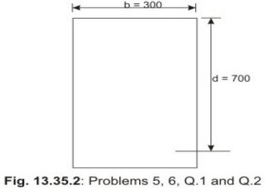
Problem 5. Design a singly-reinforced rectangular beam to carry the design moment = 100 kNm using M 25 concrete and Fe 415 grade of steel. Use b = 300 mm and d = 700 mm (Fig. 13.35.2) as preliminary dimensions.
Solution 5.
Steps 1 and 2 are not needed as the preliminary dimension of b = 300 mm and d = 700 mm are given.
Step 3. The balanced moment of resistance of the beam = Mb = Rb d2= (1.11) (300) (700) (700) = 163.17 kNm
(taking Rb = 1.11 from Table 13.3 for σcbc = 8.5 N/mm2 and σst = 230 N/mm2).
The balanced area of steel = pt, bal (bd) / 100 = (0.53) (300) (700) / 100 = 1113 mm2 (taking pt, bal = 0.53 per cent from
Table 13.4 for σcbc = 8.5 N/mm2 and σst = 230 N/mm2). We provide 4-16 mm diameter bars of Ast = 804 mm2 〈 1113 mm2 to have
pt = 804 (100) / (300) (700) = 0.383 per cent. This is more than the minimum tensile steel = 0.85 bd / fy = 430.12 mm2, as stipulated in cl. 26.5.1.1 of IS 456.
Step 4. Now, the section has to be checked for the stresses in concrete and steel, fcbc and fst, respectively.
For this problem m = 93.33 /σcbc = 10.98 and pt = 0.383 per cent, obtained in Step 3. Equation 13.16 gives:
k = - (pt m /100) + {(pt m/100)2 + (pt m /50)}1/2 = 0.251.
So, j = 1 – k/3 = 1 – 0.251/3 = 0.916. Equation 13.24 gives: fst = M / {Ast d (1-k/3)}= 100 (106) / (804) (700) (0.916) = 193.98 N/mm2 〈 230 N/mm2.
Equation 13.25 gives: fcbc = 2 Ast fst / b kd = 2(804) (193.98) / (300) (0.251) (700) = 5.92 N/mm2 〈 8.5 N/mm2
Therefore, the beam having b = 300 mm, d = 700 mm and Ast = 4-16 mm diameter bars is safe.
Problem 6. Design the singly-reinforced rectangular beam of Problem 5 (Fig. 13.35.2) by using tables of SP-16.
Solution 6.
Given data are: M = 100 kNm, b = 300 mm and d = 700 mm. M/bd2 = 100 (106) / (300) (700) (700) = 0.6803. Using Table 70 of SP-16, we get pt = 0.321, which gives Ast = 0.321 (300) (700)/100 = 674 mm2. This area of steel is the minimum amount of steel required to resist the design moment of 100 kNm. In fact, we have several alternatives of selecting area of steel from 674 mm2 to the balanced area of steel = 1113 mm2, as obtained in Step 3 of Problem 5. While solving Problem 5 by direct computation method, steel area of 804 mm2 is selected (4-16 mm diameter bars), as the amount is less than the balanced area of steel = 1113 mm2 . However, selecting area of 674 mm2 is difficult as 3-16 mm diameter bars have the area of steel 603 mm2. Only one 12 mm diameter is to be added to give additional area of 113 mm2, which satisfies the requirement. However, 12 mm bars are normally not preferred in beams. So, for the practical considerations, we prefer 4-16 mm diameter bars, as assumed in the direct computation method.
The other alternatives are changing the depth of the beam. For studying all these options, use of tables of SP-16 is very much time-saving.
Moreover, in the direct computation method, the selected area of steel has to be checked so that it is more than the minimum area of steel, as stipulated in cl. 26.5.1.1 of IS 456. On the other hand, the areas obtained from the table of SP-16 already take care so that they are more than the minimum area of steel.
Problem 7. Determine the area of steel of the beam of Problem 3 to carry a design moment of 200 kNm. The relevant data of Problem 3 are: b = 350 mm, d = 600 mm, D = 650 mm (Fig. 13.35.1) σ cbc = 7 N/mm2 and σ st = 140 N/mm2.
Solution 7.
The moment of resistance of the balanced beam = 152.46 kNm obtained by using Rb = 1.21 in the equation Mb = Rb bd2, in part b of the solution of Problem 3. The balanced area of the steel = 2100 mm2, which is taken from the solution of part b of Problem 3. The values of m = 13.33, kb = 0.4, jb = 0.87 and pt, bal = 1 are also taken from the solution of part b of Problem 3.
It is evident that the design moment (= 200 kNm) being greater than balanced moment (= 152.46 kNm), a doubly-reinforced beam has to be designed. The additional moment M′ is obtained from Eq.13.26, as
M′ = M - Mb = 200 – 152.46 = 47.54 kNm.
The additional tensile steel, obtained from Eq.13.35, is: Ast2 = M′ /σst (d-d′) = 47.54 (106)/140 (600–50) = 617.4 mm2 (assuming d′ = 50 mm).
The amount of compression steel, obtained from Equation 13.36 is: Asc = (Ast2) / (σ st)/{σ cbc(1.5m -1)(1- d′ /kd)} = (617.4)(140)/7(18.995)(0.792) = 820.79 mm2.
Total area of steel, obtained from Eq.13.33 is Ast = Ast1 + Ast2 = 2100 + 617.4 = 2717.4 mm2.
Problem 8. Solve Problem 7 (Fig. 13.35.1) using tables of SP-16.
Solution 8.
The data of Problem 7 are: b = 350 mm, d = 600 mm, D = 650 mm, σcbc = 7 N/mm2 and σst = 140 N/mm2. We assume d′ = 50 mm, as in Problem 7.
The design of doubly-reinforced beam is vary simple with the help of tables of SP-16. There are two ways. One is the direct solution using the appropriate table from Tables 72 to 79. The other option is to determine Ast1 and Ast2 from the equations and then to obtain Asc from Table M of SP-16. Both the methods are explained below.
Method 1: Here, the appropriate table is Table 73. From the values of M/bd2 and d′ /d, we get the percentages of tensile (total) and compressive reinforcement Ast and Asc. Thereafter, the total tensile area of steel and compression area of steel are determined.
M/bd2 = 200(106) / (350) (600) (600) = 1.59 and d′/d = 50/600 = 0.083.
All tables from 72 to 79 of SP-16 have step values of M/bd2 and d′/d. So, the linear interpolations are to be done three times. The adjacent M/bd2 and d′/d are 1.55 and 1.60, and 0.05 and 0.1. First, we carry out linear interpolation for d′/d = 0.5. For M/bd2 = 1.59 (when d′/d = 0.5)
pt = 1.253 + (0.038 / 0.05) 0.04 = 1.2834 and
pc = 0.305 + (0.045 /0.05) 0.04 = 0.341
Again for M/bd2 = 1.59, when d′/d = 0.1
pt = 1.267 + (0.04/0.05) (0.04) = 1.299 and
pc = 0.375 + (0.056 / 0.05) (0.04) = 0.4198.
Now, the linear interpolation is done for M/bd2 = 1.59 and d′/d = 0.083. The results are given below:
pt = 1.2834 + (0.033) (1.299 – 1.2834) / 0.05 = 1.2936
pc = 0.341 + (0.033) (0.4198 – 0.341) / 0.05 = 0.404
Thus, we have area of total tensile steel, Ast = (1.2936) (350) (600)/100 = 2716.56 mm2 and the area of compression steel, Asc = 0.404 (350) (600)/100 = 848.4 mm2. In the above calculations, more number of digits are taken to minimise the truncation error.
We get almost the same values of Ast and Asc for Problem 7 by direct computation method (same as those of Problem 8). They are as follows: Ast = 2717.4 mm2 and Asc = 820.79 mm2. The values are reasonably comparable.
Method 2: Here, in this method the values of Ast1 and Ast2 are obtained by direct computation as in Problem 7 giving Ast1 = 2100 mm2 and Ast2 = 617.4 mm2. Table M of SP-16 gives the ratio of Asc to Ast2 for different d′/d ratios. For d′/d = 0.083, by linear interpolation, we get
Asc / Ast2 = 1.2 + (0.2) (0.333)/(0.05) = 1.332
So, Asc = (1.332) (617.4) = 822.37 mm2. This value is close to that of direct computation method as the ratio is depending on Ast2 obtained by direct computation method.
13.35.3 Practice Questions and Problems with Answers
Q.1: Design the beam of Problem 5 of sec. 13.35.2 (Fig. 13.35.2) using σcbc = 8.5 N/mm2 and σst = 140 N/mm2. The given data of Problem 5 are: b = 300 mm, d = 700 mm and M = 100 kNm.
A.1: Steps 1 and 2 are not needed as preliminary dimensions of b and d are given.
Step 3.
Mb = Rb bd2 = (1.47) (300) (700) (700) = 216.09 kNm (Using Rb = 1.47 from Table 13.3). Ast, bal = pt, bal (bd/100) = (1.21) (300) (700) / 100 = 2541 mm2 (using pt, bal = 1.21 from Table 13.4). We provide 4-20 + 2-16 (=1256 + 402 = 1658 mm2) as Ast, giving pt = 1658 (100) / (300) (700) = 0.79 per cent. The minimum area of steel = 0.85 bd / fy = (0.85) (300) (700) / 250 = 714 mm2 〈1658 mm2. Hence, ok.
Step 4. Check for stresses With the modular ratio m = 93.33 /8.5 = 10.98 and pt = 0.79; Eq. 13.16 gives: k = - (pt m/100) + {(pt m/100)2 + (pt m/50)}1/2 = 0.339 ; and j = 1- k/3 = 0.887.
Equation 13.24 gives: fst = M /{Ast d (1 – k/3)} = 100(106) / (1658) (700) (0.887) = 97.14 N/mm2 〈 140 N/mm2 Equation 13.25 gives: fcbc = 2 Ast fst / bkd = 2(1658) (97.14) / (300) (0.339) (700) = 4.53 N/mm2 〈 8.5 N/mm2.
Hence, this design is ok. In fact, there are several possible alternatives as explained in the solution of Problem 5. These alternatives are obtained quickly using tables of SP-16.
Q.2: Design the beam of Q.1 (Fig. 13.35.2) using tables of SP-16.
A.2: Steps 1 and 2 are not needed as the given data are: b = 300 mm, d = 700 mm and M = 100 kNm.
Step 3.
M/bd2 = 100(106) / (300) (700) (700) = 0.6803. Table 70 of SP-16 gives pt = 0.53775 by linear interpolation. Accordingly, Ast = (0.53775) (300) (700)/100 = 1129.275 mm2. Provide 4-20 mm diameter bars of area 1256 mm2, which has pt = 1256 (100) / (300) (700) = 0.598
Step 4. Check for stresses
The modular ratio m = 10.98, k = 0.339 and j = 0.887 from A.1 of Q.1. Equation 13.24 gives: fst = M/Ast d(j) = 100 (106) / (1256) (700) (0.887) = 128.23 N/mm2 〈 140 N/mm2. Equation 13.25 gives: fcbc = 2Ast fst / b kd = (2) (1256) (128.23) / (300) (0.339) (700) = 4.52 N/mm2 〈 8.5 N/mm2 . Hence, the design is ok.
Q.3: The problem of Q.4 of sec. 3.6.11 of Lesson 6 (Fig. 3.6.4) has the following data: b = 300 mm, d = 550 mm, D = 600 mm, Mu, lim = 220.45 kNm, Ast, lim = 1107.14 mm2, M 20 and Fe 500.
(a) Determine the balanced moment of resistance and Ast,b in working stress method.
(b) Determine the areas of steel required to resist the design moment = Mu,lim /1.5 = 146.97 kNm.
A.3: (a) To determine Mb and Ast, b
Mb = Rb bd2 = (0.99) (300) (550) (550) = 89.84 kNm (using Rb = 0.99 from Table 13.3).
Using pt, bal = 0.39 from Table 13.4, Ast, b = (0.39) bd/100 = 643.5 mm2.
(b) Design of doubly-reinforced beam
From Eq.13.26: M′ = 146.97 – 89.84 = 57.13 kNm. From Eq.13.34: Ast1 = 643.5 mm2 for the balanced moment of 89.84 kNm (see sol.a of this question when pt, bal = 0.39).
From Eq .13.35: Ast 2 = M′ /σ st (d - d′ ) = (57.13) (106)/ (275) (500) = 415.49 mm2 (assuming d′ = 50 mm).
Total Ast = Ast1 + Ast2 = 643.5 + 415.49 = 1058.99 mm2.
From Eq.13.36, Asc = (Ast2) (σst) / {(σcbc) (1.5 m – 1) (1- d′ /kd)} = (415.49)(275) / {(7) (18.995) (0.636)} = 1350.36 mm2.
The bea m requ ires Ast = 1058.99 mm2 and Asc = 1350.36 mm2. In the limit state method the values are: Ast = 1107.14 mm2 and Asc = 0, i.e., only singlyreinforced beam with almost the same amount of Ast is sufficient. This shows the economy in the design when done by employing limit state method.
This problem, however, cannot be solved by using tables of SP-16 as the tables of SP-16 do not have the values for Fe 500 grade of steel.
13.35.4 Limitations of Working Stress Method
The basis of the analysis by the working stress method is very simple. This method was used for the design of steel and timber structures also. However, due to the limitations of the method, now the limit state methods are being used. The limitations of working stress method are the following:
i) The assumptions of linear elastic behaviour and control of stresses within specially defined permissible stresses are unrealistic due to several reasons viz., creep, shrinkage and other long term effects, stress concentration and other secondary effects.
ii) The actual factor of safety is not known in this method of design. The partial safety factors in the limit state method is more realistic than the concept of permissible stresses in the working stress method to have factor of safety in the design.
iii) Different types of load acting simultaneously have different degrees of uncertainties. This cannot be taken into account in the working stress method.
Accordingly, the working stress method is gradually replaced by the limit state method. The Indian code IS 456 has given working stress method in Annex B to give greater emphasis to limit state design. Moreover, cl. 18.2.1 of IS 456 specifically mentions of using limit state method normally for structures and structural elements. However, cl.18.2.2 recommends the use of working stress method where the limit state method cannot be conveniently adopted. Due to its simplicity in the concept and applications, better structural performance in service state and conservative design, working stress method is still being used for the design of reinforced concrete bridges, water tanks and chimneys. In fact, design of tension structures and liquid retaining structures are not included in IS 456 for the design guidelines in the limit state method of design.
Accordingly, Lessons 34 and 35 include the basic concept of this method. The design of T-beam in flexure, rectangular and T-beams under shear, torsion and other topics of the limit state method, covered in different lessons, are not included adopting working stress method. However, the designs of tension structures and liquid retaining structures are taken up in the next lesson, as these are not included by the limit state method.
13.35.6 Test 35 with Solutions
Maximum Marks = 50,
Maximum Time = 30 minutes
Answer all questions.
TQ.1: Problem 4.1 of sec. 4.9.2 of Lesson 4 has the following data: (Fig. 4.9.1) b = 300 mm, d = 630 mm, d′ = 70 mm, D = 700 mm, M 20, Fe 415, Mu, lim = 492.96 kNm, Ast1 =1809.14 mm2, Ast2 = 783.621 mm2 (Ast = 2572.834 mm2), Asc = 806.517 mm2 (by direct computation method). Tension steel reinforcement = 4-25 mm diameter bars + 2-20 mm diameter bars (= 2591 mm2) and compression steel reinforcement = 2-20 mm diameter bars + 2-12 mm diameter bars (= 854 mm2).
Determine the areas of steel by working stress method when the design moment = Mu, lim / 1.5 = 328.64 kNm. Use the same dimensions of the beam as mentioned above. Use direct computation method and also tables of SP-16.
A.TQ.1: (1) Direct computation method
Given data are: b = 300 mm, d = 630 mm, σcbc = 7 N/mm2 and σst = 230 N/mm2.
Mb = Rb bd2 = 0.91 (300) (630) (630) = 108.35 kNm (using Rb = 0.91 from Table 13.3). Therefore, M′ = M – Mb = 328.64 – 108.35 = 220.29 kNm.
Ast b = pt, bal (bd/100) = 0.44 (300) (630) / 100 = 831.6 mm2 (using pt, bal = 0.44 from Table 13.4) and Ast2 = M′ / {σ st (d-d′ )} = 220.29 (106) / {(230) (630 – 70)} = 1710.32 mm2. Therefore, Ast = 831.6 + 1710.32 = 2541.92 mm2.
The modular ratio m = 93.33 / σcbc = 13.33 and kb = 93.33/(σst +93.33) = 0.289.
Asc =(Ast2) (σ st) / {σ cbc (1.5 m –1) (1-d′ /kd) = 4806.37 mm2 , giving pc = Asc (100)/ bd = (4806.37) (100) / (300) (630) = 2.54 per cent 〈 maximum percentage allowed (4 per cent) as per cl.26.5.1.2 of IS 456.
So, Ast = 2541.92 mm2 = (4-25 + 2-20 giving 2591 mm2) and Asc =4806.37 mm2 = (8-25 + 3-20 giving 4869 mm2)
(2) Using tables of SP-16
M/bd2 = 328.64 (106) / (300) (630) (630) = 2.76 d′/d = 70/630 = 0.11
Table 77 has the values of pt and pc for different values of M/bd2 and d′ /d. Therefore, the final values of pt and pc are to be determined by carrying out the linear interpolation three times, as explained in the solution of Problem 8. The results are given below:
(a) For Mu/bd2 = 2.75, d′/d = 0.11
pt = 1.327 + 0.052 (0.01) / 0.05 = 1.3374
pc = 2.348 + 1.03 (0.01) / 0.005 = 2.555
(b) For Mu/bd2 = 2.8 and d′/d = 0.11
pt = 1.351 + (0.053) (0.01) / 0.05 = 1.3616
pc = 2.412 + (1.063) (0.01) / 0.05 = 2.6246
(c) Therefore, for Mu/bd2 = 2.76 and d′/d = 0.11
pt = 1.3374 + (0.0342) (0.01) / (0.05) = 1.34424
pc = 2.555 + (0.0696) (0.01) / (0.05) = 2.5689
So, Ast = (1.34424) (300) (630) / 100 = 2540.6 mm2
and Asc = (2.5689) (300) (630) / 100 = 4855.2 mm2.
The values of Ast = 2541.92 mm2 and Asc = 4806.37 mm2, obtained by direct computation method in part (1) of this problem, are reasonably comparable with the values obtained by using tables of SP-16.
Summary of this Lesson
This lesson illustrates the applications of the equations developed in Lesson 34 for the analysis and design of singly and doubly-reinforced rectangular beams by working stress method. For this purpose, several numerical problems are solved. Some of the problems have the same dimensions of width and effective depth but with different grades of steel so that the results are compared. Moreover, problems solved earlier on singly and doubly-reinforced beams are also taken up to compare the results. The method of direct computation i.e., using the appropriate equations directly and the use of tables of SP-16 are employed for some of the problems to illustrate the simplicity in using the tables of SP-16. Several practice problems, test problem and illustrative examples will help in understanding the applications for the analysis and design of singly and doubly-reinforced rectangular beams.
FAQs on Numerical Problems - Working Stress Method - Civil Engineering (CE)
| 1. What is the working stress method in civil engineering? |  |
| 2. How is the maximum allowable stress determined in the working stress method? | |
| 3. What are the advantages of using the working stress method in civil engineering design? | |
| 4. What are the limitations of the working stress method in civil engineering design? | |
| 5. How does the working stress method ensure structural safety and performance? | |


video lectures
,Previous Year Questions with Solutions
,Numerical Problems - Working Stress Method - Civil Engineering (CE)
,Numerical Problems - Working Stress Method - Civil Engineering (CE)
,Numerical Problems - Working Stress Method - Civil Engineering (CE)
,Free
,Extra Questions
,practice quizzes
,study material
,Summary
,Exam
,past year papers
,Semester Notes
,mock tests for examination
,Objective type Questions
,Viva Questions
,shortcuts and tricks
,Important questions
,ppt
,Sample Paper
,MCQs
;


Numerical Problems - Working Stress Method Free PDF Download
Importance of Numerical Problems - Working Stress Method
Numerical Problems - Working Stress Method Notes
Numerical Problems - Working Stress Method Civil Engineering (CE) Questions
Study Numerical Problems - Working Stress Method on the App
|
© EduRev
|
Education Revolution
|


|


