Obtaining Internal Forces in a System: General Procedure and Internal Force Diagrams - Civil Engineering (CE) PDF Download

Obtaining Internal Forces in a System: General Procedure
The general method of obtaining internal forces at certain cross-section of a system under a given loading (and support) condition is by applying the concepts of equilibrium (Lecture 2). To illustrate, let us consider the beam-column AB in Figure 2.7 for which we have to find the internal forces at section a - a . As we have learned earlier, equilibrium conditions are best studied through free body diagrams. We can find the reactions at supports A and B using a free body diagram of the whole beam-column AB (Figure 2.8). We solve the three equations for static equilibrium for this free body:
∑Fx=Ax - 2kN =0
∑Fy=Ay -2kN - 3kN +By =0
∑Mz (about A)= By (12m) - 3kN (10m) -2kN (6m)=0
Ax =2kN
Ay =1.5 kN
By =3.5 kN
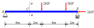
Figure 2.7 Loading and support conditions for planar beam-column system AB
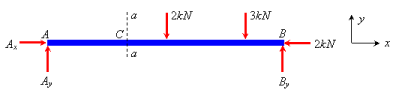
Figure 2.8 Free body diagram of AB
If a system is in static equilibrium condition, then every segment of it is also in equilibrium. So,we can consider the equilibrium for each of AC or CB independently. Let us consider the equilibrium of part AC,and draw its free body diagram (Figure 2.9).In addition to externally applied forces and the support reaction Ax and Ay ,this free body is acted upon by forces P ,V and M on the surface a - a .These are nothing but the internal forces (axial force, shear force and bending moment, respectively) acting at the cross-section a - a of AB .Note that these forces are drawn in their respective positive directions in order to avoid sign confusion. Solving the three static equilibrium equations for AC we find these internal forces:
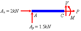
Figure 2.9 Free body diagram of part AC
∑Fx = P + 2kN
∑Fy =V+1.5kN =0
∑Mz (aboutC) = M-1.5kN(4m)=0
P=-2kN
V=-1.5kN
M=6kNm
Thus we obtain the internal forces at section a - a .These could also be obtained by considering the equilibrium of the part at the other side of section a - a ,that is of part CB. Figure 2.10 shows the free body diagram of CB .Again,the internal forces are drawn in their positive directions on surface a - a ,which is a negative x-surface for this free body. Solving the three equations we find the values for these internal forces:
∑Fx = P + 2kN =0
∑Fy= -V - 2kN - 3kN + 3.5kN =0
∑Mz (aboutC) = -M -2kN(2m) -3kN (6m) +3.5kN (8m)=0
P= -2kN
V= -1.5kN
M= 6kNm
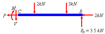
Figure 2.10 Free body diagram of part CB
Note that these values match exactly with the values obtained previously by considering the equilibrium of segment AC .This is true for any system because there is always a unique set of internal forces on an internal surface for a given loading condition.
Internal Force Diagrams
Let us consider the beam-column AB of the previous example with the same loading condition, but a different cross-section b - b (Figure 2.11).Following the same procedure as in the previous example we can find the internal forces at b - b .The values of internal forces at b - b are not same as of those at a - a.
P = -2kN
V = 0.5kN
M = 8kNm
Thus, internal forces vary according to the cross-section under consideration.
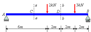
Figure 2.11 Cross-section b - b of beam column AB
A structural member should be able to carry the internal forces at each section without failure so as to perform its intended function. So, in order to check the integrity or effectiveness of a structural member, one needs to check its capacity against internal forces at its each and every cross-section.This makes the study of the variation of internal forces in a member very important to Structural Mechanics.Such a study is best done through internal force diagrams, which provide,at one glance, several critical information on these internal forces.
We use individual diagrams for each type of internal force.Thus we have axial force diagram,shear force diagram and bending moment diagram for a beam.For the beam-column AB of Figure 2.7,we can find internal forces at each cross section and obtain the internal force diagrams. Figure 2.12 shows three internal force diagrams for this beam.
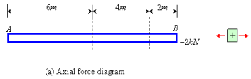
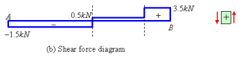
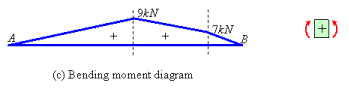
Figure 2.12 Axial force (a), shear force (b) and bending moment (c) diagrams for AB
Note that, we have marked +ve and –ve signs in these diagrams and also put our sign convention to define the direction of the internal force under consideration.In addition to that, it is also important that we label these diagrams with values at key points (that means, the maximum positive and negative value points, zero-value points, points where the variation changes, for example from linear to parabolic).
FAQs on Obtaining Internal Forces in a System: General Procedure and Internal Force Diagrams - Civil Engineering (CE)
| 1. What is the general procedure for obtaining internal forces in a system? |  |
| 2. How can I draw an internal force diagram for a system? | |
| 3. What are some common types of internal forces in civil engineering systems? | |
| 4. How important is it to accurately determine internal forces in civil engineering designs? | |
| 5. What are some challenges in obtaining internal forces in civil engineering systems? | |


Extra Questions
,Objective type Questions
,Obtaining Internal Forces in a System: General Procedure and Internal Force Diagrams - Civil Engineering (CE)
,Viva Questions
,mock tests for examination
,video lectures
,shortcuts and tricks
,Summary
,study material
,Sample Paper
,Obtaining Internal Forces in a System: General Procedure and Internal Force Diagrams - Civil Engineering (CE)
,MCQs
,Semester Notes
,past year papers
,Free
,Obtaining Internal Forces in a System: General Procedure and Internal Force Diagrams - Civil Engineering (CE)
,ppt
,Important questions
,practice quizzes
,Exam
,Previous Year Questions with Solutions
;


Obtaining Internal Forces in a System: General Procedure and Internal Force Diagrams Free PDF Download
Importance of Obtaining Internal Forces in a System: General Procedure and Internal Force Diagrams
Obtaining Internal Forces in a System: General Procedure and Internal Force Diagrams Notes
Obtaining Internal Forces in a System: General Procedure and Internal Force Diagrams Civil Engineering (CE) Questions
Study Obtaining Internal Forces in a System: General Procedure and Internal Force Diagrams on the App
|
© EduRev
|
Education Revolution
|


|


within 7 days!