Oscillators - 1 | Analog Circuits - Electronics and Communication Engineering (ECE) PDF Download
Oscillators
- Oscillators are electronic circuits that generate an output signal without the necessity of an input signal. It produces a periodic waveform on its output with only the DC supply voltage as an input.
- It produces a periodic waveform on its output with only the DC supply voltage as an input.
- Different types of oscillators produce various types of outputs including sine waves, square waves, triangular waves, and sawtooth waves.
- The basic structure of a sinusoidal oscillator consists of an amplifier and a frequency selective network connected in a positive feedback loop as shown in figure 1.
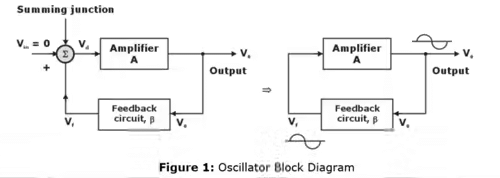
In the block diagram of figure 1,
Vd = Vf + Vin
V0 = AVd
Vf = βV0
Using these relationships, the following equation is obtained:
However, Vin = 0 and V0 ≠ - implies that,
Expressed in polar form
Equation (i) & (ii) gives two requirements for oscillation:
- The magnitude of the loop gain Aβ must be at least 1, and
- The total phase shift of the loop gain Aβ must be equal to 0° or 360°.
The above conditions is known as Barkhausen criterion.
In figure 1, if the amplifier causes a phase shift of 180°, the feedback circuit must provide an additional phase shift of 180° so that the total phase shift around the loop is 360°. The type of waveform generated by an oscillator depends on the components in the circuit hence may be sinusoidal, square or triangular. In addition, the frequency of oscillation is determined by the components in the feedback circuit.
Oscillators can be of 2 types:
- Feedback Oscillators:
- One type of oscillator is the feedback oscillator, which returns a fraction of the output signal to the input with no net phase shift, resulting in a reinforcement of the output signal.
- After oscillations are started, the loop gain is maintained at 1.0 to maintain oscillations.
- A feedback oscillator consists of an amplifier for gain (either a discrete transistor or an op-amp) and a positive feedback circuit that produces phase shift and provides attenuation.
- Relaxation Oscillators:
- Instead of feedback, a relaxation oscillator uses an RC timing circuit to generate a waveform that is generally a square wave or other non sinusoidal waveform.
- Typically, a relaxation oscillator uses a Schmitt trigger or other device that changes states to alternately charge and discharge a capacitor through a resistor.
Oscillation with RC Feedback Circuits
- Three types of feedback oscillators that use RC circuits to produce sinusoidal outputs are the:
(i) Wien-bridge oscillator
(ii) Phase-shift oscillator
(iii) Twin-T oscillator - Generally, RC feedback oscillators are used for frequencies up to about 1 MHz.
- The Wien-bridge is by far the most widely used type of RC feedback oscillator for this range of frequencies.
Wien Bridge Oscillator
Because of its simplicity and stability, one of the most commonly used audio-frequency oscillators is the wein bridge. Figure 2 shows the wein bridge oscillator in which the wein bridge circuit is connected between the amplifier input terminals and the output terminal. The bridge has a series RC network in one arm and a parallel RC network in adjoining arm. In the remaining two arms of the bridge, resistors R1 and R2 are connected.
The phase angle criterion for oscillation is that the total phase shift around the circuit must be 0°. This condition occurs only when the bridge is balanced, that is at resonance. the frequency of oscillation f0 is exactly the resonant frequency of the balanced wein bridge and is given by:
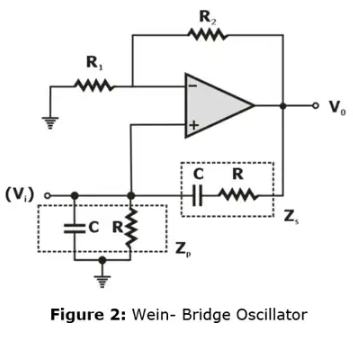
Assuming that the resistors are equal in value, and capacitors are equal in value in the reactive leg of the wein bridge. At this frequency the gain required for sustained oscillation is given by
A = 1/β = 3
That is
or
Phase-shift Oscillator
- A phase-shift oscillator relies upon an R-C phase shift network to provide the necessary phase relationship between output and input to a CE amplifier. The frequency of oscillation is given by and the phase shift is 180o.
- Phase-shift Oscillator using Op-Amp
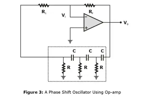 The op-amp is used in the inverting mode; therefore, any signal that appears at the inverting terminal is shifted by 180° at the output. An additional 180° phase sift required for oscillation is provided by the cascaded RC networks. Thus, the total phase shift around the loop is 360° (or 0°). At some specific frequency when the phase shift of the cascaded RC networks is exactly 180° and the gain of the amplifier is sufficiently large, the circuit will oscillate at the frequency. This frequency is called the frequency of oscillation f0 and is given by
At this frequency, the gain A must be at least 29.
This is,
or
- For the loop gain βA to be greater than unity, the gain of the amplifier stage must be greater than 1/β or 29.
A > 29
- For the loop gain βA to be greater than unity, the gain of the amplifier stage must be greater than 1/β or 29.
- Phase-shift Oscillator using FET
Here an FET amplifier of conventional design is followed by three cascaded arrangements of a capacitor C and a resistor R, the output of the last RC combination being returned to the gate. If the loading of the phase-shift network on the amplifier can be neglected, the amplifier shifts by 180° the phase of any voltage which appears on the gate, and the network of resistors and capacitors shifts the phase by an additional amount. At some frequency the phase-shift introduced by the RC network will be precisely 180° and at this frequency the total phase-shift from the gate around the circuit and back to the gate will be exactly zero. This particular frequency will be the one at which the circuit will oscillate, provided that the magnitude of the amplification is sufficiently large.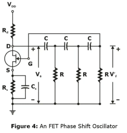 The frequency of oscillation for this circuit is given by
At the frequency of oscillation, In order that |βA| shall not be less than unity, it is required that |A| be at least 29. Hence and FET with μ < 29 cannot be made to oscillate in such a circuit.
 - Phase Shift Oscillator using Transistor
- At low frequencies (around 100 kHz or less), resistors and capacitors are usually employed to determine the frequency of oscillation, if the phase shift through the common-emitter amplifier is 180o, then the oscillation may occur at the frequency, where the RC network produces and addition 180o phase shift.
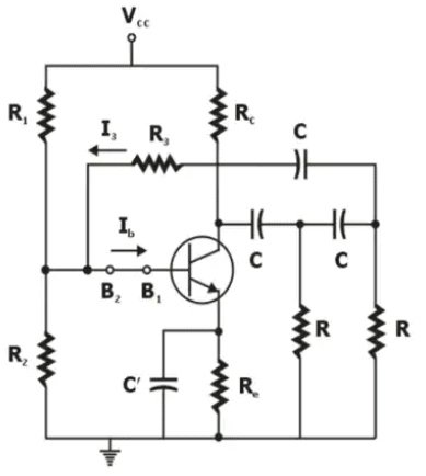 Figure 5: Transistor Phase shift oscillatorThe frequency of oscillation is given by
Where, K = RC/R. The condition for sustaining of oscillation is given by
(Note: The value of K which gives the minimum hfe turns out to be 2.7 and for this optimum value of RC/R, we find hfe = 44.5.)
- At low frequencies (around 100 kHz or less), resistors and capacitors are usually employed to determine the frequency of oscillation, if the phase shift through the common-emitter amplifier is 180o, then the oscillation may occur at the frequency, where the RC network produces and addition 180o phase shift.
Oscillators with LC Feedback Circuits
- Although the RC feedback oscillators, particularly the Wien bridge, are generally suitable for frequencies up to about 1 MHz, LC feedback elements are normally used in oscillators that require higher frequencies of oscillation.
- Also, because of the frequency limitation (lower unity-gain frequency) of most op-amps, transistors (BJT or FET) are often used as the gain element in LC oscillators.
- This section introduces several types of resonant LC feedback oscillators like the Colpitts, Clapp, Hartley & crystal-controlled oscillators.
The Colpitts Oscillator
- This type of oscillator uses an LC circuit in the feedback loop to provide the necessary phase shift and to act as a resonant filter that passes only the desired frequency of oscillation.
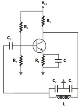 Colpitts Oscillator using BJT
 - The approximate frequency of oscillation is the resonant frequency of the LC circuit and is established by the values of C1, C2 and L, and according to the formula:

- Where CT is the total capacitance. Because the capacitors effectively appear in series around the tank circuit, the total capacitance CT is

Drawback of Colpitts oscillator
f0 is unstable due to the effect of internal capacitances.
net input capacitance Ci appears in parallel with C1 and net output capacitance C0 appears in parallel with C2. As a result.
where, C1 = C1 + Ci ; C2 = C2 + C0.
Since, Ci and C0 vary with time and temperature, f0 becomes unstable. To eliminate this drawback an additional capacitance C3 can be connected in series with inductor. Such circuit is called clapp oscillator.
The Clapp Oscillator
- The Clapp oscillator is a variation of the Colpitts. The basic difference is an additional capacitor, C3 in series with the inductor in the resonant feedback circuit.
- Since C3 is in series with C1 and C2 around the tank circuit, the total capacitance is

- and the approximate frequency of oscillation Q > 10, is

- If C3 is much smaller than C1 and C2 then C3 almost entirely controls the resonant frequency

- Clapp provides a more accurate and stable frequency of oscillation
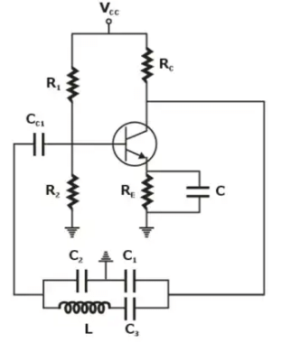 Figure 7: Clapp OscillatorsFrequency of oscillation
If C3 is selected such that it is much smaller than then
Thus,
f0 becomes independent of C1 and C2.
|
3 videos|75 docs|64 tests
|
FAQs on Oscillators - 1 - Analog Circuits - Electronics and Communication Engineering (ECE)
| 1. What is an oscillator in electronics and communication engineering? |  |
| 2. What are the different types of oscillators used in electronics and communication engineering? |  |
| 3. What is the importance of oscillators in electronics and communication engineering? |  |
| 4. How does an oscillator work? |  |
| 5. What factors affect the frequency stability of an oscillator? |  |


