Performance of Transmission Lines | Electrical Engineering SSC JE (Technical) - Electrical Engineering (EE) PDF Download
TRANSMISSION LINE
Classification: On the basis of length of transmission line, the transmission lines are divided into three categories:
- Short transmission lines
- Medium transmission lines
- Long transmission lines
1. SHORT TRANSMISSION LINE
A transmission is defined as a short transmission if its length is less than 80 km.
Assumptions :
- The shunt capacitance effect is negligible.
- The line parameters could be assumed to be lumped.
Equivalent Circuit:
- Under balanced conditions, the line can be represented by the equivalent circuit of a single phase with resistance R and inductive reactance XL in series.
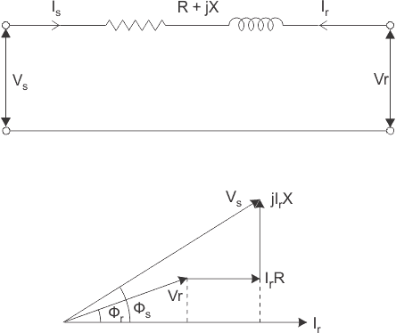
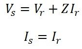
Sending end parameters Is = Ir, Vs = Vr + IrZ
Where Is, Vs are sending end current and voltage and Ir, Vr are the receiving end current and voltage respectively and Z is the impedance of transmission line.
In matrix from

VOLTAGE REGULATION:
- Voltage regulation of a line is defined as the rise in the receiving end voltage when full load at a specified power factor is removed while the sending end voltage is kept constant.
% voltage regulation = 
Where Vs is the sending voltage or no load receiving end voltage and Vr is full load rated receiving end voltage.
- From phasor diagram of shunt transmission line, the sending end voltage
Where fr is the phase angle at receiving end.
Voltage regulation = 
Note:
- In above equation, fr is positive for lagging power factor load and negative for leading power factor load.
Remember:
- The power factor has a great influence on the voltage regulation; for lagging power factor the regulation is positive and for leading power factors may even by negative.
- Condition for zero voltage regulation Ir R cosfr = Ir XL sinf
or tan r = (R/x)
EFFICIENCY:
The ratio of power at the receiving end to the power at the sending end is known as efficiency of the transmission line.
% efficiency = (Power delivered at he receiving end / Power sent from the sending end) x 100
ABCD PARAMETERS:
The sending end quantities Vs, Is can be represented in terms of receiving end quantities Vr, Ir by the following equations.

Vs = AVr + BIr
Is = CVr + DIr
- A: It is the voltage impressed at the sending end per volt at the receiving end when receiving end is open. It is dimensionless.

- B: It is the voltage impressed at the sending end to have one ampere of current at the short circuited receiving end. This is known as transfer impedance.

- C: It is the current in amperes into the sending end per volt on the open-circuited receiving end.
This is known as transfer admittance.

- D: It is the current at the sending end for one amperes of current at the short circuited receiving end.

- In matrix form s
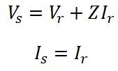
- ABCD parameters of short transmission line A = 1, B = Z, C = 0, D = 1
- Efficiency of short transmission line:

where P is the power received at the receiving end and R is the resistance per phase of the line.
2. MEDIUM TRANSMISSION LINE
A transmission line is defined as medium transmission line if it has length between 80 km and 240 km and its single phase equivalent circuit can be represented as nominal p or nominal T circuit configuration.
Assumption:
- The line parameters are lump parameters.
Nominal Circuit
- The shunt admittance is assumed to be concentrated in the middle while the series impedance is split into two equal parts.
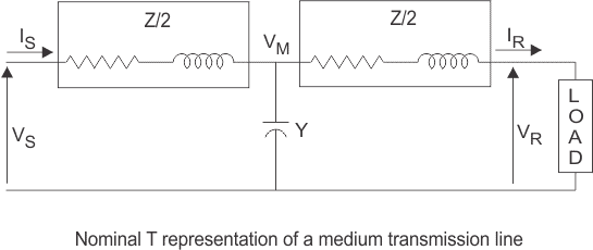
- The sending end parameters in terms of receiving end parameters
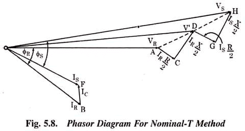
- In matrix form

- A, B, C, D parameters
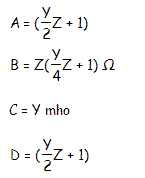
∴

- Current in shunt branch

- Voltage across the shunt branch

Nominal π Circuit:
- One half of the total capacitance of each conductor is placed at each end.
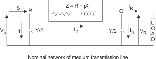
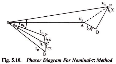
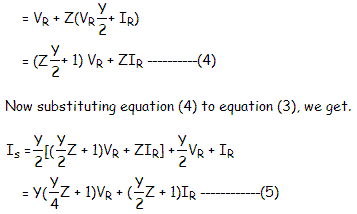
- The sending end parameters in terms of receiving end parameters.
VS = A Vr + Z*Ir
- In matrix form

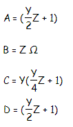
- A, B, C, D parameters
3. LONG TRANSMISSION LINE
A transmission line is defined as long transmission line if it has length greater than 240 km.
- Line parameters are distributed uniformly over the entire length.
Assumptions:
- The line is operating under sinusoidal, balanced, steady-state conditions.
- The line is transposed.
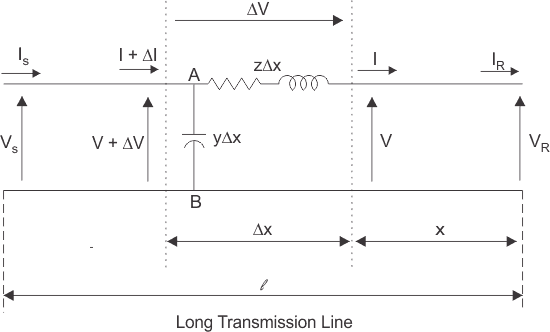
- In the above figure V(x) and I(x) denotes the phasor voltage and phasor current at location x on the line from the receiving end.
- The series impedance per-unit length Z = R + jwL.
Where R and L are series resistance and inductance per unit length. - The shunt admittance per unit-length Y = G + jwC.
Where G and C are shunt conductance and capacitance to neutral per unit length
Here a line of length l > 250km is supplied with a sending end voltage and current of VS and IS respectively, whereas the VR and IR are the values of voltage and current obtained from the receiving end. Lets us now consider an element of infinitely small length Δx at a distance x from the receiving end as shown in the figure where.
- V = value of voltage just before entering the element Δx.
- I = value of current just before entering the element Δx.
- V+ΔV = voltage leaving the element Δx.
- I+ΔI = current leaving the element Δx.
- ΔV = voltage drop across element Δx.
- zΔx = series impedance of element Δx
- yΔx = shunt admittance of element Δx
Where, Z = z l and Y = y l are the values of total impedance and admittance of the long transmission line.
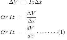
Therefore, the voltage drop across the infinitely small element Δx is given by
Now to determine the current ΔI, we apply KCL to node A.
Since the term ΔV yΔx is the product of 2 infinitely small values, we can ignore it for the sake of easier calculation.Therefore, we can write

Now derivating both sides of eq (1) w.r.t x,
Now substituting from equation (2)

The solution of the above second order differential equation is given by.
Derivating equation (4) w.r.to x.

Now comparing equation (1) with equation (5)
Now to go further let us define the characteristic impedance Zc and propagation constant δ of a long transmission line as
Then the voltage and current equation can be expressed in terms of characteristic impedance and propagation constant as

Now at x=0, V= VR and I= Ir. Substituting these conditions to equation (7) and (8) respectively.
Solving equation (9) and (10),We get values of A1 and A2 as,
Now applying another extreme condition at x = l, we have V = VS and I = IS.
Now to determine VS and IS we substitute x by l and put the values of A1 and
A2 in equation (7) and (8) we get
By trigonometric and exponential operators we know
Therefore, equation (11) and (12) can be re-written as
Thus compared with the general circuit parameters equation, we get the ABCD parameters of a long transmission line as,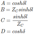
FERRANTI-EFFECT
When a long line is operating under no load or light load condition, the receiving end voltage is greater than the sending end voltage. This is known as Ferranti-effect.
Remember:
- Usually the capacitive reactance of the line is quite large as compared to the inductive reactance.
- Under no load or lightly loaded condition the line current is of leading power factor (pf).

- The charging current (IC) produces drop in the reactance of the line which is in phase opposition to the receiving end voltage.
Remember:
- If the reactive power generated at a point is more than the reactive power absorbed, the voltage at that point becomes higher than the normal value and vice versa.
- Inductive reactance of the transmission line is a sink for the reactive power when as the shunt capacitances generate reactive power.
- If the line loading corresponds to the surge impedance loading, the voltage is same every where as the reactive power absorbed equals the reactive power generated by the line.
Remember:
- If loading is less than SIL (surge impedance loading), the reactive power generated is more than absorbed.
POWER FLOW
- In above figure the sending end bus is fed by generator and the receiving end bus feeds to the load. Sr, Ss is the complex power at the receiving end and sending end respectively.
- Let receiving end voltage Vr = |Vr| ∠0° Sending ed voltage Vs = |Vs| ∠d°, A = D = |A| ∠a°, B = |B| ∠b°
- Receiving end current in terms of Vs, Vr and ABCD parameters


- The complex power per phase at the receiving end

- Sending end current in terms of Vs, Vr, and ABCD parameters

- The complex power per phase at the sending end or power infected injected by generator

Important Observations:
- The above equations yield power per phase if the phase voltage are used for Vs and Vr.
The total power is three times the power per phase.
- The above equations yield 3-f power directly if Vs and Vr represent line to line voltage.
Real and Reactive Power
At receiving end
At sending end
- For fixed value of Vs and Vr the receiving end real power is maximum whend =b

- The load must draw the leading Vars to achieve condition of maximum real power at the receiving end.
For short transmission line

the transmission line has very small resistance as compared to inductive reactance.


Important Conclusion:
- For fixed values of Vs, Vr and X the real power depends on power angle d which is the phase angle between Vs and Vr. Power can be transferred over the line even when |Vs| = |Vr|.
- A decrease in inductance increases the line capacity.
- Inductance can be decreased by using double circuit lines and by use of bundled conductor line.
|
23 videos|89 docs|42 tests
|
FAQs on Performance of Transmission Lines - Electrical Engineering SSC JE (Technical) - Electrical Engineering (EE)
| 1. What is the purpose of transmission lines in electrical engineering? |  |
| 2. What are the main factors that affect the performance of transmission lines? |  |
| 3. How do transmission line losses affect power transmission? |  |
| 4. What is the significance of impedance matching in transmission lines? |  |
| 5. How does the skin effect impact the performance of transmission lines? |  |


