Q1: A 10(1/2) digit timer counter possesses a base clock of frequency 100 MHz. When measuring a particular input, the reading obtained is the same in: (i) Frequency mode of operation with a gating time of one second and (ii) Period mode of operation (in the x 10 ns scale). The frequency of the unknown input (reading obtained) in Hz is _______. (SET-2 (2017))
(a) 100
(b) 1000
(c) 10000
(d) 100000
Ans: (c)
Sol: 1.
(10(1/2)) digital time counter:
Frequency mode of operation: f = n/t
Let f = frequency of input signal
n = number of cycles of repetitive signal
⇒ 100 × 106
Let t ⇒ Gate time ⇒ t = 1sec.
 = 108cycles/sec
On 10(1/2) digit display
100000000.00Hz
2.
Period mode of operation:
 Let P = Period of input signal
P = 0.01 × 10−6
= 10 × 10−9
= 1 × 10n−sec
= 10.000000000n − sec
Q2: A stationary closed Lissajous pattern on an oscilloscope has 3 horizontal tangencies and 2 vertical tangencies for a horizontal input with frequency 3 kHZ. The frequency of the vertical input is (SET-2 (2017))
(a) 1.5kHz
(b) 2kHz
(c) 3kHz
(d) 4.5kHz
Ans: (d)
Sol:  ⇒ fy = 4.5 kHz
Q3: The slope and level detector circuit in a CRO has a delay of 100 ns. The start-stop sweep generator has a response time of 50 ns. In order to display correctly, a delay line of (SET-1 (2017))
(a) 150 ns has to be inserted into the y-channel
(b) 150 ns has to be inserted into the x-channel
(c) 150 ns has to be inserted into both x and y channels
(d) 100 ns has to be inserted into both x and y channels
Ans: (a)
Sol: A delay line of 150ns has to be inserted into the y-channel to get synchronous between sweep signal applied to x-plate and test signal applied to y-plate.
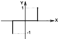
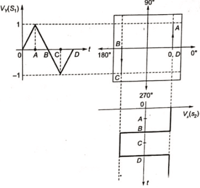
Q4: The two signals S1 and S2, shown in figure, are applied to Y and X deflection plates of an oscilloscope.
 The waveform displayed on the screen is (SET-3(2014))
(a)  (b)
(b)  (c)
(c)  (d)
(d)  Ans: (a)
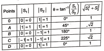
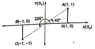
Sol: The waveform pattern appearing on the screen of CRO is shown below. Here, S1 is applied to vertical deflecting plate and S2 to horizontal deflecting plate.


Q5: In an oscilloscope screen, linear sweep is applied at the (SET-1 (2014)
(a) vertical axis
(b) horizontal axis
(c) origin
(d) both horizontal and vertical axis
Ans: (b)
Sol: A CRO uses a horizontal input voltage which is an internally generated ramp voltage (i.e. linear sweep voltage) called "Time base of CRO". An oscilloscope is used to disply waveform which varies as a function of time. To reproduce the waveform accurately, the beam must have a constant horizontal velocity i.e. the deflecting voltage must increase linearly with time. This voltage is called a ramp voltage. Thus , a sawtooth waveform also called linear sweep voltage is applied to the horizontal deflection system ( or horizontal axis) which provides a time base to CRO.
Q6: A 4(1/2) digit DMM has the error specification as: 0.2% of reading + 10 counts. If a dc voltage of 100 V is read on its 200 V full scale, the maximum error that can be expected in the reading is (2011)
(a) ±0.1%
(b) ±0.2%
(c) ±0.3%
(d) ±0.4%
Ans: (c)
Sol: 4(1/2)digit
 No. of full digits in case of 4(1/2) digit display = 4
So, maximum count with 4(1/2) digits display = 20,000
Full scale reading = 200V
1 count = 200V/20,000
E1= Error corrsponding to 10 counts = 10 x (200/20,000) = 0.1 V
Reading = 100V
Error corresponding to 0.2% of reading
E2 = 0.2 × (100/100) = 0.2V
Total error = E1 + E2
= 0.1 + 0.2 = 0.3V i.e.0.3%.
Q7: A dual trace oscilloscope is set to operate in the ALTernate mode. The control input of the multiplexer used in the y-circuit is fed with a signal having a frequency equal to (2011)
(a) the highest frequency that the multiplexer can operate properly
(b) twice the frequency of the time base (sweep) oscillator
(c) the frequency of the time base (sweep) oscillator
(d) half the frequency of the time base (sweep) oscillator
Ans: (c)
Q8: An average-reading digital multi-meter reads 10 V when fed with a triangular wave, symmetric about the time-axis. For the same input an rms-reading meter will read (2009)
(a) 20/√3
(b) 10/√3
(c) 20√3
(d) 10√3
Ans: (a)
Sol: For triangular wave,
Average value = Vm/2
RMS value = Vm/√3
∴ Vm/2 =10V ⇒ Vm = 20
RMS value = Vm/√3 = 20/√3 V
Q9: The two inputs of a CRO are fed with two stationary periodic signals. In the X-Y mode, the screen shows a figure which changes from ellipse to circle and back to ellipse with its major axis changing orientation slowly and repeatedly. The following inference can be made from this. (2009)
(a) The signals are not sinusoidal
(b) The amplitudes of the signals are very close but not equal
(c) The signals are sinusoidal with their frequencies very close but not equal
(d) There is a constant but small phase difference between the signals
Ans: (d)
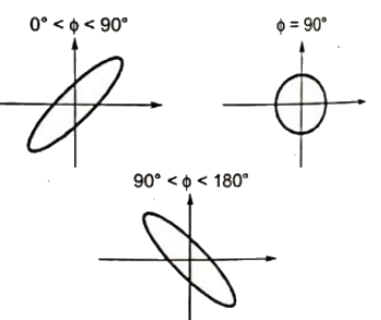
Sol:  Because phase difference only patterns changes from ellipse to circle and back to ellipse.
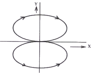
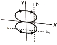
Q10: Two sinusoidal signals p(ω1t) = Asinω1t and q(ω2t) are applied to X and Y inputs of a dual channel CRO. The Lissajous figure displayed on the screen shown below : The signal q(ω2t) will be represented as (2008)
 (a) q(ω2t) = Asinω2t, ω2 = 2ω1
(b) q(ω2t) = Asinω2t, ω2 = ω1/2
(c) q(ω2t) = Acosω2t, ω2 = 2ω1
(d) q(ω2t) = Acosω2t, ω2 = ω1/2
Ans: (d)
Sol: Here, P(ω1t) = Asinω1t
y1-line cut '4' times the Lissajous pattern
x1-line cut '2' times the Lisaajous pattern
 ωy/ωx = (maximum number of intersection of a horizontal line with Lissajous pattern)/(maximum number of intersection of a vertical line with Lissajous pattern)
 ∴ ωx = 2ωy
ω1 = 2ω2
and q(ω2, t) will lead q(ω1, t) by 90° as trace is a circle
q(ω2, t) = Asin(ω2t + 90°)
q(ω2, t) = A cos ω2t
Q11: Two 8-bit ADCs, one of single slope integrating type and other of successive approximate type, take TA and TB times to convert 5 V analog input signal to equivalent digital output. If the input analog signal is reduced to 2.5 V, the approximate time taken by the two ADCs will respectively, be (2008)
(a) TA, TB
(b) TA/2, TB
(c) TA, TB/2
(d) TA/2, TB/2
Ans: (b)
Sol: Single slope integrating type ADC utilize digital counter techniques to measure time required for a voltage ramp to rise from zero to the input voltage.
If conversion time for input voltage 5V = TA
So, conversion time for input voltage 2.5V = TA/2
Conversion time in successive type ADC does not depend on input voltage. So, conversion time for input voltage 2.5V is also TB.
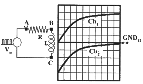
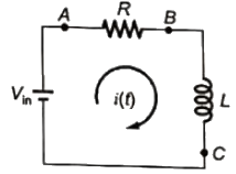
Q12: The probes of a non-isolated, two channel oscillocope are clipped to points A, B and C in the circuit of the adjacent figure. Vin is a square wave of a suitable low frequency. The display on Ch1 and Ch1 are as shown below. Then the "Signal" and "Ground" probes S1, G1 and S2, G2 of Ch1 and Ch1 respectively are connected to points : (2007)
 (a) A, B, C, A
(b) A, B, C, B
(c) C, B, A, B
(d) B, A, B, C
Ans: (b)
Sol: Square wave is of low frequency. So, it can be assumed that time during which the wave forms are displayed on the screen, the voltage across R and L is Vin


 So, S1 is connected to point A.
and, G1 is connected to point B.
Voltage across inductor = VBC = L(di/dt)

 So, S2 is connected to point C.
and G2 is connected to point B.
Q13: The time/div and voltage/div axes of an oscilloscope have been erased. A student connects a 1 kHz, 5 V p-p square wave calibration pulse to channel-1 of the scope and observes the screen to be as shown in the upper trace of the figure. An unknown signal is connected to channel-2(lower trace) of the scope. It the time/ div and V/div on both channels are the same, the amplitude (p-p) and period of the unknown signal are respectively (2006)
 (a) 5 V, 1 ms
(b) 5 V, 2 ms
(c) 7.5 V, 2 ms
(d) 10 V, 1 ms
Ans: (c)
Sol: Peak-peak (p-p) division of upper trace voltage = 2 and value of (p-p) voltage = 5V
∴ Voltage/Division = 2.5V
Now it will be same for unknown voltage (p-p) division of unknown voltage = 3
Therefore, p-p voltage 3 × 2.5 = 7.5V
Frequency of upper trace = 1 kHz
∴Time period = 1/103 = 1ms
Division of x-axis(upper) = 4
Division of x-axis(lower) = 8
Therefore, Period of unknown signal = 2ms
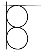
Q14: The simultaneous application of signals x(t) and y(t) to the horizontal and vertical plates, respectively, of an oscilloscope, produces a vertical figure of 8 display. If P and Q are constants and X(t) = Psin(4t + 30°), then y(t) is equal to (2005)
(a) Q sin(4t−30°)
(b) Q sin(2t+15°)
(c) Q sin(8t+60°)
(d) Q sin(4t+30°)
Ans: (b)
Sol: fy = frequency of signal applied to y plates
fx = frequency of signal applied to x plates
x(t) = Psin(4t + 30)
So, fx = 4/2π Hz

 Q sin(2t + 15) has angular frequency.
ω = 2rad/sec
Q15: A digital-to-analog converter with a full-scale output voltage of 3.5 V has a resolution close to 14 mV. Its bit size is (2005)
(a) 4
(b) 8
(c) 16
(d) 32
Ans: (b)
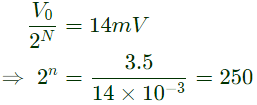
Sol: Resolution of digital to analog coverter
R = V0/2N = 14mV
Where,
V0 = Full scale output voltage = 3.5V
N = bit-size
 N = 8
N = 8
Q16: The Q-meter works on the principle of (2005)
(a) mutual inductance
(b) self inductance
(c) series resonance
(d) parallel resonance
Ans: (c)
Sol: Q = ω0L/R
where ω0 is the resonant angular frequency, L is the inductance and R is the effective resistance of the coil.
The priciple of working of Q-meter is based upon series resonance of R, L, C circuit.
Q17: A CRO probe has an impedance of 500kΩ in parallel with a capacitance of 10 pF. The probe is used to measure the voltage between P and Q as shown in figure. The measured voltage will be (2004)
 (a) 3.53 V
(b) 4.37 V
(c) 4.54 V
(d) 5.00 V
Ans: (b)
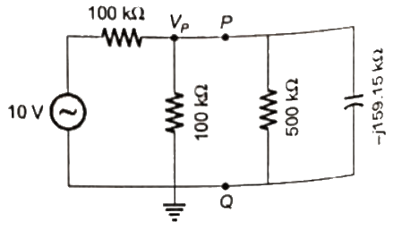
Sol: 

 Taking supply voltage as the reference
Vs = 10∠0V
Using KCL,
 Vp = 4.37∠ −15.94V
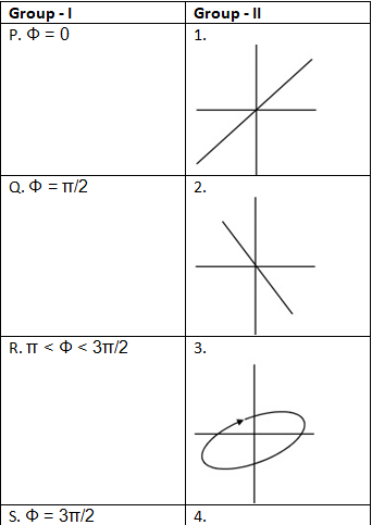
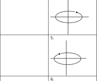
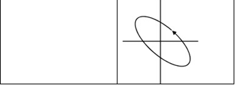
Q18: Group-II represents the figures obtained on a CRO screen when the voltage signals Vx = Vxm sin ωt and Vy = Vym sin(ωt + Φ) are given to its X and Y plates respectively and Φ is changed. Choose the correct value of Φ from Group-I to match with the corresponding figure of Group-II (2003)


 (a) P-1, Q-3, R-6, S-5
(b) P-2, Q-6, R-4, S-5
(c) P-2, Q-3, R-5, S-4
(d) P-1, Q-5, R-6, S-4
Ans: (d)
Sol: when two voltages are in phase i.e. [ϕ = 0° or 180°], the trace is straight line. But for ϕ = 0°, the trace has positive slope and ϕ = 180°, the trace has negative slope.
When the two voltage has phase displacement of ϕ = 90°, the trace is a circle. If the direction of the trace is in the clockwise direction then the phase difference is ϕ = 90°.
If the direction of the trace is anti-clockwise direction the phase difference is (2π−ϕ) = (2π−(π/2)) = 3(π/2)
When the difference is not equal to 0° or 90°, the trace is an ellipse. For π ≤ ϕ ≤ (3π/2), the trace is an ellipse in anti-clockwise direction.
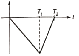
Q19: The simplified block diagram of a 10-bit A/D converter of dual slope integrator type is shown in figure. The 10-bit counter at the output is clocked by a 1 MHz clock. Assuming negligible timing overhead for the control logic, the maximum frequency of the analog signal that can be converted using this A/D converter is approximately (2003)
 (a) 2kHz
(b) 1kHz
(c) 500Hz
(d) 250Hz
Ans: (b)
Sol: The wave form of dual slope integrater is shown. The maximum frequency can be attained when T2 − T1 = 0 and as
 T1 = 2NTC (TC = clock period)

Q20: A reading of 120 is obtained when standard inductor was connected in the circuit of a Q-meter and the variable capacitor is adjusted to value of 300 pF. A lossless capacitor of unknown value Cx is then connected in parallel with the variable capacitor and the same reading was obtained when the variable capacitor is readjusted to a value of 200 pF. The value of Cx in pF is (2003)
(a) 100
(b) 200
(c) 300
(d) 500
Ans: (a)
Sol: Q of the coil = 120
 CASE-I:
Q = 120 is obtained for C = 300pF
CASE-II:
For the same reading i.e. Q = 120
Effective capacitance of the circuit shuold be 300 pF.
Effective capacitance of parallel capacitor
Ceff = C + Cx
Cx = Ceff - C
= 300 -200 = 100pF
Q21: Two in-phase, 50 Hz sinusoidal waveform of unit amplitude are fed into channel 1 and channel 2 respectively of an oscilloscope. Assuming that the voltage scale, time scale and other settings are exactly the same for both the channels, what would be observed if the oscilloscope is operated in X-Y mode? (2002)
(a) A circle of unit radius
(b) An ellipse
(c) A parabola
(d) A straight line inclined at 45° with respect to the x-axis
Ans: (d)
Sol: ∴ Phase difference = 0° also fx = fy.
 = 108cycles/sec
 Let P = Period of input signal
 ⇒ fy = 4.5 kHz
 The waveform displayed on the screen is (SET-3(2014))
 (b)
(b) 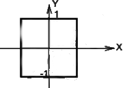 (c)
(c) 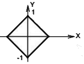 (d)
(d) 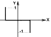 Ans: (a)
 No. of full digits in case of 4(1/2) digit display = 4
 Because phase difference only patterns changes from ellipse to circle and back to ellipse.
 (a) q(ω2t) = Asinω2t, ω2 = 2ω1
 ωy/ωx = (maximum number of intersection of a horizontal line with Lissajous pattern)/(maximum number of intersection of a vertical line with Lissajous pattern)
 ∴ ωx = 2ωy
 (a) A, B, C, A
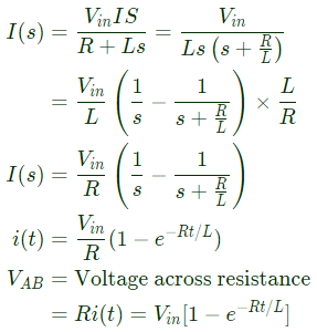
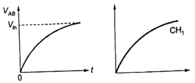 So, S1 is connected to point A.
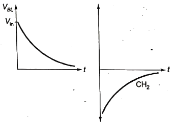 So, S2 is connected to point C.
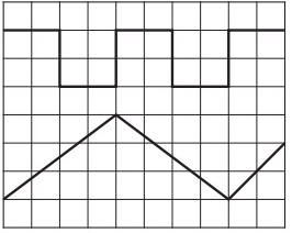 (a) 5 V, 1 ms
 Q sin(2t + 15) has angular frequency.
 N = 8
N = 8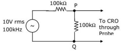 (a) 3.53 V

 Taking supply voltage as the reference
 Vp = 4.37∠ −15.94V
 (a) P-1, Q-3, R-6, S-5
 (a) 2kHz
 T1 = 2NTC (TC = clock period)
 CASE-I:


