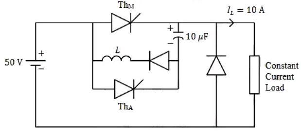
Q1: A forced commutated thyristorized step-down chopper is shown in the figure. Neglect the ON-state drop across the power devices. Assume that the capacitor is initially charged to 50 V with the polarity shown in the figure. The load current (IL) can be assumed to be constant at 10 A. Initially, ThM is ON and ThA is OFF. The turn-off time available to ThM in microseconds, when ThA is triggered, is _____ (rounded off to the nearest integer). (2024)
 (a) 45
(b) 50
(c) 58
(d) 62
Ans: (b)
Sol: 

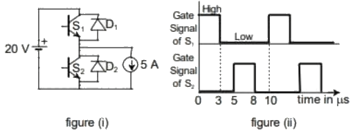
Q2: The chopper circuit shown in figure (i) feeds power to a 5 A DC constant current source. The switching frequency of the chopper is 100kHz. All the components can be assumed to be ideal. The gate signals of switches S1 and S2 are shown in figure (ii). Average voltage across the 5 A current source is (2023)
 (a) 10 V
(b) 6 V
(c) 12 V
(d) 20 V
Ans: (b)
Sol: Output Voltage Waveform :
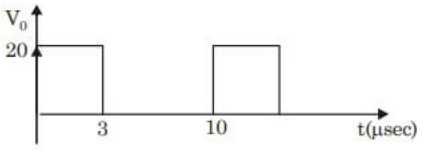 ∴ Average voltage,
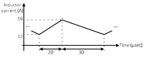
Q3: The steady state current flowing through the inductor of a DC-DC buck boost converter is given in the figure below. If the peak-to-peak ripple in the output voltage of the converter is 1 V, then the value of the output capacitor, in μF, is _______________. (round off to nearest integer) (2022)
 (a) 124
(b) 148
(c) 165
(d) 182
Ans: (c)
Sol: We have for buck boost converter,
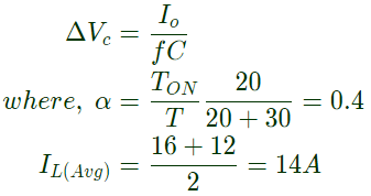 For buck-boost converter,
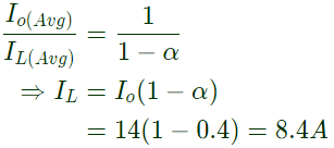

Q4: Consider the buck-boost converter shown. Switch Q is operating at 25 kHz and 0.75 duty-cycle. Assume diode and switch to be ideal. Under steady-state condition, the average current flowing through the indicator is ____________A. (2021)
 (a) 15
(b) 18
(c) 30
(d) 24
Ans: (d)
Sol: 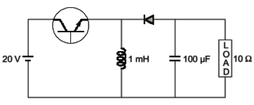 α = 0.75, f = 25kHz
Assume continous conduction:
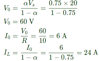

 ∴ Continous conduction assumption is correct.
IL = 24 A
Q5: Consider the boost converter shown. Switch Q is operating at 25 kHz with a duty cycle of 0.6. Assume the diode and switch to be ideal. Under steady-state condition, the average resistance Rin as seen by the source is __________ Ω.
(Round off to 2 decimal places). (2021)
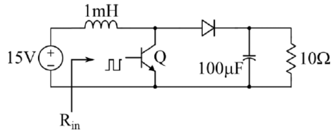 (a) 1.25
(b) 1.6
(c) 2.2
(d) 3.45
Ans: (b)
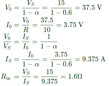
Sol: Checking for continuous conduction mode
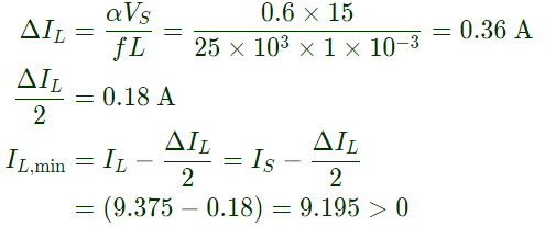 As it is continuous conduction
Q6: In the dc-dc converter circuit shown, switch Q is switched at a frequency of 10 kHz with a duty ratio of 0.6. All components of the circuit are ideal, and the initial current in the inductor is zero. Energy stored in the inductor in mJ (rounded off to 2 decimal places) at the end of 10 complete switching cycles is ________. (2020)
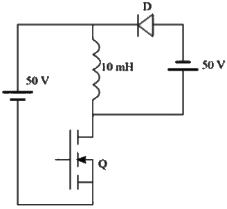 (a) 10
(b) 5
(c) 15
(d) 20
Ans: (b)
Sol: Buck boost converter,
D = 0.6→store energy

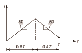 For one cycle: Rise in current for 0.2T
For 10 cycles: Find rise in current (0.2T) × 10 = 2T

 ∴ Energy stored
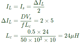
Q7: In a DC-DC boost converter, the duty ratio is controlled to regulate the output voltage at 48 V. The input DC voltage is 24 V. The output power is 120 W. The switching frequency is 50 kHz. Assume ideal components and a very large output filter capacitor. The converter operates at the boundary between continuous and discontinuous conduction modes. The value of the boost inductor (in μH) is _______. (2019)
(a) 12
(b) 24
(c) 28
(d) 14
Ans: (b)
Sol: 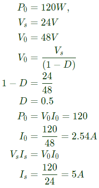 At boundary of continuous and discontinuous,
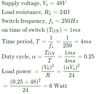
Q8: A DC-DC buck converter operates in continuous conduction mode. It has 48 V input voltage, and it feeds a resistive load of 24 Ω. The switching frequency of the converter is 250 Hz. If switch-on duration is 1 ms, the load power is (2019)
(a) 6 W
(b) 12 W
(c) 24 W
(d) 48 W
Ans: (a)
Sol: Geven that,
Q9: A dc to dc converter shown in the figure is charging a battery bank, B2 whose voltage is constant at 150 V. B1 is another battery bank whose voltage is constant at 50 V. The value of the inductor, L is 5 mH and the ideal switch, S is operated with a switching frequency of 5 kHz with a duty ratio of 0.4. Once the circuit has attained steady state and assuming the diode D to be ideal, the power transferred from B1 to B2 (in Watt) is ___________ (up to 2 decimal places). (2018)
 (a) 8
(a) 8
(b) 10
(c) 12
(d) 16
Ans: (c)
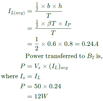
Sol: 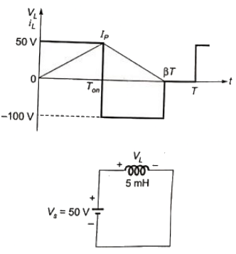 During Ton the circuit behaves as,
 Integrating on both sides,
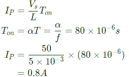
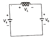
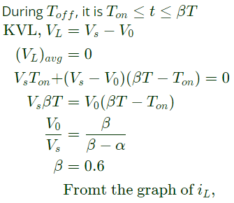
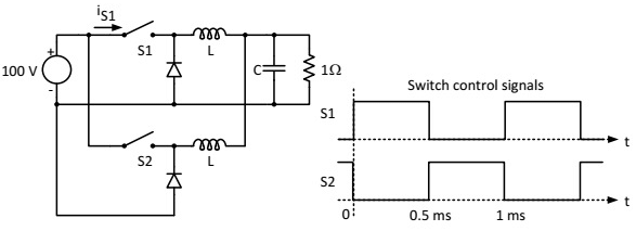
Q10: The figure shows two buck converters connected in parallel. The common input dc voltage for the converters has a value of 100 V. The converters have inductors of identical value. The load resistance is 1 Ω. The capacitor voltage has negligible ripple. Both converters operate in the continuous conduction mode. The switching frequency is 1 kHz, and the switch control signals are as shown. The circuit operates in the steady state. Assuming that the converters share the load equally, the average value of iS1, the current of switch S1 (in Ampere), is _____ (up to 2 decimal places). (2018)
 (a) 5.55
(b) 6.85
(c) 7.25
(d) 12.50
Ans: (d)
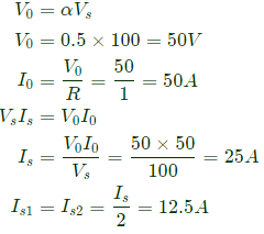
Sol: Hence it is buck converter,
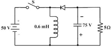
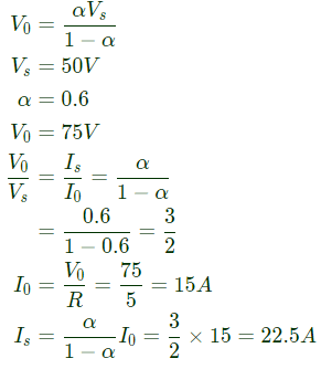
Q11: In the circuit shown all elements are ideal and the switch S is operated at 10 kHz and 60% duty ratio. The capacitor is large enough so that the ripple across it is negligible and at steady state acquires a voltage as shown. The peak current in amperes drawn from the 50 V DC source is ________. (Give the answer up to one decimal place.) (SET-2 (2017))
 (a) 37
(b) 40
(c) 22
(d) 56
Ans: (b)
Sol: Buckboost converter,
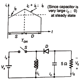 Since capacitor is very large ic = 0 at steady state
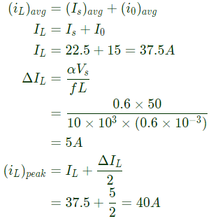 Peak value of current drawn from source = (iL)peak = 40A
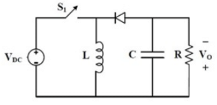
Q12: The input voltage VDC of the buck-boost converter shown below varies from 32 V to 72 V. Assume that all components are ideal, inductor current is continuous, and output voltage is ripple free. The range of duty ratio D of the converter for which the magnitude of the steady state output voltage remains constant at 48 V is (SET-1 (2017))
 (a)
(a) 
(b) 
(c) 
(d) 
Ans: (a)
Sol: 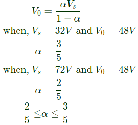

Q13: A DC-DC boost converter, as shown in the figure below, is used to boost 360V to 400 V, at a power of 4 kW. All devices are ideal. Considering continuous inductor current, the rms current in the solid state switch (S), in ampere, is _________. (SET-2 (2016))
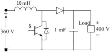 (a) 2.5
(b) 3.5
(c) 6.5
(d) 8.5
Ans: (b)
Sol: 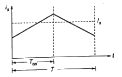
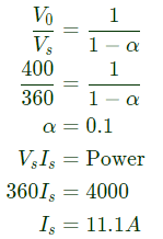 Neglecting ripple in is


Q14: A buck-boost DC-DC converter, shown in the figure below, is used to convert 24 V battery voltage to 36 V DC voltage to feed a load of 72 W. It is operated at 20 kHz with an inductor of 2 mH and output capacitor of 1000 μF. All devices are considered to be ideal. The peak voltage across the solid-state switch (S), in volt, is ____________. (SET-2 (2015))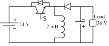 (a) 24
(b) 36
(c) 60
(d) 72
Ans: (c)
Sol: When switch 'S' is off, diode D is on then
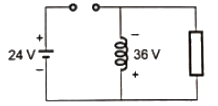 Therefore, Peak voltage across switch = 24 + 36 = 60V
Q15: A buck converter, as shown in Figure (a) below, is working in steady state. The output voltage and the inductor current can be assumed to be ripple free. Figure (b) shows the inductor voltage VL during a complete switching interval. Assuming all devices are ideal, the duty cycle of the buck converter is ________. (SET-1 (2016))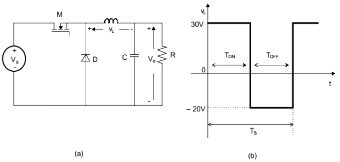 (a) 0.2
(b) 0.4
(c) 0.8
(d) 1
Ans: (b)
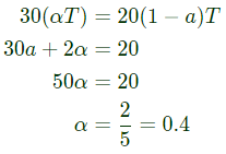
Sol: Average voltage across inductor is zero.


 (a) 45

 (a) 10 V
 ∴ Average voltage,
 (a) 124
 For buck-boost converter,

 (a) 15
 α = 0.75, f = 25kHz

 ∴ Continous conduction assumption is correct.
  (a) 1.25
 As it is continuous conduction
 (a) 10
 For one cycle: Rise in current for 0.2T
 ∴ Energy stored
 At boundary of continuous and discontinuous,

 (a) 8
(a) 8 During Ton the circuit behaves as,
 Integrating on both sides,


 (a) 5.55
 (a) 37
 Since capacitor is very large ic = 0 at steady state
 Peak value of current drawn from source = (iL)peak = 40A
  (a)
(a) 


 (a) 2.5
 Neglecting ripple in is

 (a) 24
 Therefore, Peak voltage across switch = 24 + 36 = 60V
 (a) 0.2


