Q16: Two semi-infinite dielectric regions are separated by a plane boundary at y = 0. The dielectric constants of region 1 (y < 0) and region 2 (y > 0) are 2 and 5, respectively. Region 1 has uniform electric field  where
where  are unit vectors along the x, y and z axes, respectively. The electric field in region 2 is (SET-2 (2015))
(a) 
(b) 
(c) 
(d) 
Ans: (a)
Sol: Given that,
at the interface (y = 0) there is no surface charge.
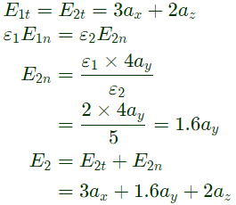
 Normal component of electric field is 4ay tangential component of electric field is 3ax + 2ay
Now, E1 = E1t + E1n
The tangentail component of E1= tangentail component of E2
Q17: A parallel plate capacitor is partially filled with glass of dielectric constant 4.0 as shown below. The dielectric strengths of air and glass are 30 kV/cm and 300 kV/cm, respectively. The maximum voltage (in kilovolts), which can be applied across the capacitor without any breakdown, is ______. (SET-1 (2015))
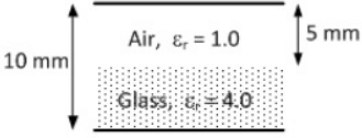 (a) 30.85
(b) 10.50
(c) 18.75
(d) 40.35
Ans: (c)
Sol: A capacitor is made as shown in figure
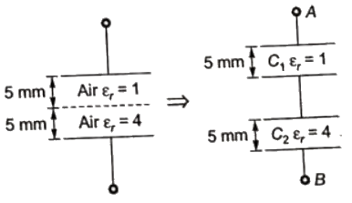 Breakdown of dielectric air is 30 kV/cm and breakdown of dielectric glass is 300 kV/cm.
We need to find maximum value of VAB so that no C1 or C2 breaks down.
Since, area and width of C1 and C2 is same but εr1 = 1 and εr2 = 4
So, C2 = 4C1
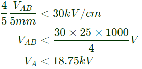
So, if VAB is applied,
 For C1 not breakdown, we need
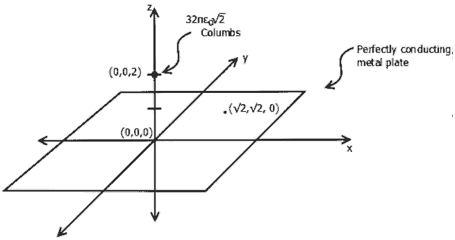
Q18: A perfectly conducting metal plate is placed in x-y plane in a right handed coordinate system. A charge of  coulombs is placed at coordinate (0, 0, 2). ε0 is the permittivity of free space. Assume
  to be unit vectors along x, y and z axes respectively. At the coordinate
  the electric field vector
  (Newtons/Coulomb) will be (SET-3 (2014))
 (a)
(a) 
(b) 
(c) 
(d) 
Ans: (b)
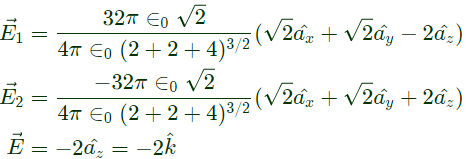
Sol: Due to change at (0, 0, 2) and conductor plane there is an image at (0, 0, -2).
Total filed is 
Q19: A hollow metallic sphere of radius r is kept at potential of 1 Volt. The total electric flux coming out of the concentric spherical surface of radius R( > r) is (SET-3 (2014))
(a) 4πε0r
(b) 4πε0r2
(c) 4πε0R
(d) 4πε0R2
Ans: (a)
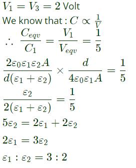
Q20: A parallel plate capacitor consisting two dielectric materials is shown in the figure. The middle dielectric slab is placed symmetrically with respect to the plates.
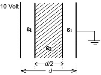 If the potential difference between one of the plates and the nearest surface of dielectric interface is 2 Volts, then the ratio ε1:ε2 is (SET-2 (2014))
(a) 1:4
(b) 2:3
(c) 3:2
(d) 4:1
Ans: (c)
Sol: Let, A = Area of plates
Let C1 = C3 be the capacitance formed with dielectric having dielectric constant ε1.
Ceqv be the equivalent capacitance.
C2 be the capacitance formed with dielectic having dielectric constant εr2.
 Also, equivalent capacitance = Ceqv
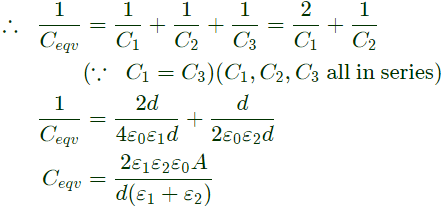 Given, Veqv = Total Voltage = 10 Volt,
Q21: C0 is the capacitance of a parallel plate capacitor with air as dielectric (as in figure (a)). If, half of the entire gap as shown in figure (b) is filled with a dielectric of permittivity ϵr, the expression for the modified capacitance is (SET-1 (2014))
 (a)
(a) 
(b) 
(c) 
(d) 
Ans: (a)
Sol: Let A be the area of the parallel plate capacitor and d be the distance between the plates.
⇒ With air dielectric:
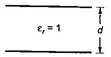 Capacitance, C0 = ε0A/D ...(i)
⇒ With the new arrangement:
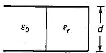 Let C1 be the capacitance of half portion with air as dielectic medium and C2 be capacitance with a dielectic of permitivity, εr.
 Now, these two capacitance will be in parallel if a voltage is applied between the plates as same potential difference will be there between both the capacitance.
 Equivalent capacitance is
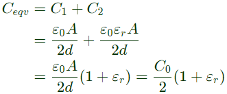 Therefore, modified capacitance,
Q22: A dielectric slab with 500 mm x 500 mm cross-section is 0.4 m long. The slab is subjected to a uniform electric field of E = 6ax + 8ay kV/mm. The relative permittivity of the dielectric material is equal to 2. The value of constant ε0 is 8.85 × 10⁻¹² F/m. The energy stored in the dielectric in Joules is (2013)
(a) 8.85 x 10⁻¹¹
(b) 8.85 x 10⁻⁵
(c) 88.5
(d) 885
Ans: (c)
Sol: Energy density 
Energy = Energy density x Volume
Energy 

Q23: A capacitor is made with a polymeric dielectric having an εr of 2.26 and a dielectric breakdown strength of 50 kV/cm. The permittivity of free space is 8.85 pF/m. If the rectangular plates of the capacitor have a width of 20 cm and a length of 40 cm, then the maximum electric charge in the capacitor is (2011)
(a) 2μC
(b) 4μC
(c) 8μC
(d) 10μC
Ans: (c)
Sol:
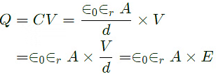 = 8.85 x 10-12 x 2.26 x 20 x 10-2 x 40 x 10-2 x 5000 x 103
= 8μC
Q24: Two point charges Q1 = 10μC and Q2 = 20μC are placed at coordinates (1, 1, 0) and (-1, -1, 0) respectively. The total electric flux passing through a plane z = 20 will be (2008)
(a) 7.5 μC
(b) 13.5 μC
(c) 15.0 μC
(d) 22.5 μC
Ans: (c)
Sol: Net electrical flux passing thriugh plane Z = 20

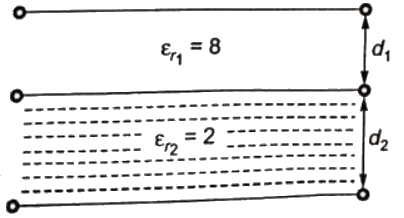
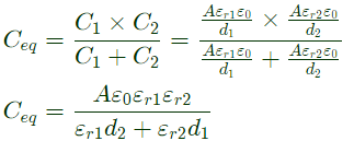
Q25: A capacitor consists of two metal plates each 500 x 500 mm2 and spaced 6 mm apart. The space between the metal plates is filled with a glass plate of 4 mm thickness and a layer of paper of 2 mm thickness. The relative primitivities of the glass and paper are 8 and 2 respectively. Neglecting the fringing effect, the capacitance will be (Given that ε0 = 8.85 × 10⁻¹² F/m ) (2008)
(a) 983.3 pF
(b) 1475 pF
(c) 6637.5 pF
(d) 9956.25 pF
Ans: (b)
Sol: 

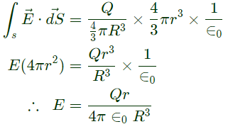
Q26: A solid sphere made of insulating material has a radius R and has a total charge Q distributed uniformly in its volume. What is the magnitude of the electric field intensity, E, at a distance r(0 < r < R) inside the sphere ? (2007)
(a) 
(b) 
(c) 
(d) 
Ans: (a)
Sol: By Gauss's theorem
 where, Qenclosed in radius r
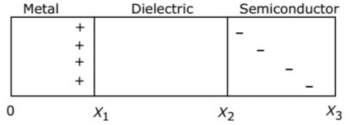
Q27: The charge distribution in a metal-dielectric-semiconductor specimen is shown in the figure. The negative charge density decreases linearly in the semiconductor as shown. The electric field distribution is as shown in (2005)
 (a)
(a) 
(b) 
(c) 
(d) 
Ans: (a)
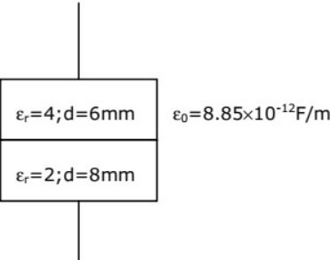
Q28: A parallel plate capacitor is shown in figure. It is made two square metal plates of 400 mm side. The 14 mm space between the plates is filled with two layers of dielectrics of εr = 4, 6 mm thick and εr = 2, 8 mm thick. Neglecting fringing of fields at the edge the capacitance is (2004)
 (a) 1298 pF
(b) 944 pF
(c) 354 pF
(d) 257pF
Ans: (d)
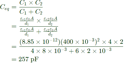
Sol: When two capacitor formed by two layer of dielectics are connected in series, then equivalent capacitance
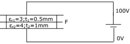
Q29: A composite parallel plate capacitor is made up of two different dielectric material with different thickness (t1 and t2) as shown in figure. The two different dielectric materials are separated by a conducting foil F. The voltage of the conducting foil is (2003)
 (a) 52 V
(b) 60 V
(c) 67 V
(d) 33 V
Ans: (b)
Sol: 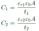 Let voltage on the conductor coil is V, then
 [Charges on both capacitor are equal]

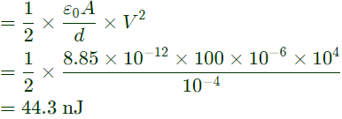
Q30: A parallel plate capacitor has an electrode area of 100 mm2, with spacing of 0.1 mm between the electrodes. The dielectric between the plates is air with a permittivity of 8.85 × 10⁻¹² F/m. The charge on the capacitor is 100 V. The stored energy in the capacitor is (2003)
(a) 8.85 pJ
(b) 440 pJ
(c) 22.1 pJ
(d) 44.3 pJ
Ans: (d)
Sol: 
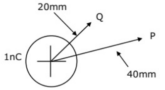
Q31: A point charge of +1 nC is placed in a space with permittivity of 8.85 × 10⁻¹² F/m as shown in figure. The potential difference VPQ between two points P and Q at distance of 40 mm and 20 mm respectively from the point charge is (2003)
 (a) 0.22 kV
(b) -225 V
(c) -2.24 kV
(d) 15 V
Ans: (b)
Sol: 

Q32: Given the potential function in free space to be V(x) = (50x2 + 50y2 + 50z2) volts, the magnitude (in volts/metre) and the direction of the electric field at a point (1, -1, 1), where the dimensions are in metres, are (2001)
(a) 
(b) 
(c) 
(d) 
Ans: (d)
Sol: 


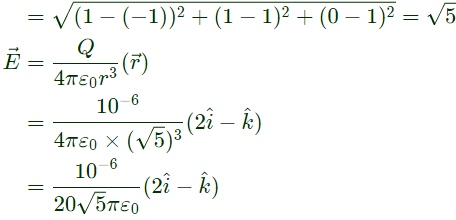
Q33: The electric field  (in volts/metre) at the point (1, 1, 0) due to a point charge of +1μC located at (-1, 1, 1) (coordinates in metres)is (2001)
(a) 
(b) 
(c) 
(d) 
Ans: (a)
Sol: 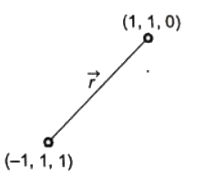
 Distance between (1, 1, 0) and (-1, 1, 1) = r
 where
where  are unit vectors along the x, y and z axes, respectively. The electric field in region 2 is (SET-2 (2015))


 Normal component of electric field is 4ay tangential component of electric field is 3ax + 2ay
 (a) 30.85
 Breakdown of dielectric air is 30 kV/cm and breakdown of dielectric glass is 300 kV/cm.
 For C1 not breakdown, we need
 coulombs is placed at coordinate (0, 0, 2). ε0 is the permittivity of free space. Assume
  to be unit vectors along x, y and z axes respectively. At the coordinate
  the electric field vector
  (Newtons/Coulomb) will be (SET-3 (2014))
 (a)
(a) 


 If the potential difference between one of the plates and the nearest surface of dielectric interface is 2 Volts, then the ratio ε1:ε2 is (SET-2 (2014))
 Also, equivalent capacitance = Ceqv
 Given, Veqv = Total Voltage = 10 Volt,
 (a)
(a) 


 Capacitance, C0 = ε0A/D ...(i)
 Let C1 be the capacitance of half portion with air as dielectic medium and C2 be capacitance with a dielectic of permitivity, εr.
 Now, these two capacitance will be in parallel if a voltage is applied between the plates as same potential difference will be there between both the capacitance.
 Equivalent capacitance is
 Therefore, modified capacitance,


 = 8.85 x 10-12 x 2.26 x 20 x 10-2 x 40 x 10-2 x 5000 x 103


 where, Qenclosed in radius r
 (a)
(a) 


 (a) 1298 pF
 (a) 52 V
 Let voltage on the conductor coil is V, then
 [Charges on both capacitor are equal]


 (a) 0.22 kV


 (in volts/metre) at the point (1, 1, 0) due to a point charge of +1μC located at (-1, 1, 1) (coordinates in metres)is (2001)


 Distance between (1, 1, 0) and (-1, 1, 1) = r


