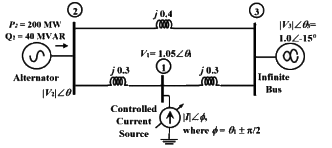
Q1: The three-bus power system shown in the figure has one alternator connected to bus 2 which supplies 200 MW and 40 MV AR power. Bus 3 is infinite bus having a voltage of magnitude ∣V3∣ = 1.0 p.u. and angle of −15°. A variable current source, ∣1∣ ∠ϕ is connected at bus 1 and controlled such that the magnitude of the bus 1 voltage is maintained at 1.05 p.u. and the phase angle of the source current,  where θ1 is the phase angle of the bus 1 voltage. The three buses can be categorized for load flow analysis as (2023)
 (a) Bus 1 Slack bus
Bus 2 P − ∣V∣ bus
Bus 3 P − Q bus
(b) Bus 1 P − ∣V∣ bus
Bus 2 P − ∣V∣ bus
Bus 3 Slack bus
(c) Bus 1 P − Q bus
Bus 2 P − Q bus
Bus 3 Slack bus
(d) Bus 1 P − ∣V∣ bus
Bus 2 P − Q bus
Bus 3 Slack bus
Ans: (d)
Sol: Concept : Classification of Bus system :
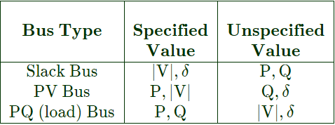 Now, from given power system network.
Bus-1 ⇒ PV bus
Bus-2 ⇒ PQ (load) bus
Bus-3 ⇒ Slack bus
Q2: Suppose IA, IB and IC are a set of unbalanced current phasors in a three-phase system. The phase-B zero-sequence current IB0 = 0.1∠0° p.u. If phase-A current IA = 1.1∠0° p.u and phase-C current IC = (1 ∠ 120° + 0.1) p.u, then IB in p.u is (2021)
(a) 1∠240° − 0.1∠0°
(b) 1.1∠240°−0.1∠0°
(c) 1.1∠−120°+0.1∠0°
(d) 1∠−120° + 0.1∠0°
Ans: (d)
Sol: 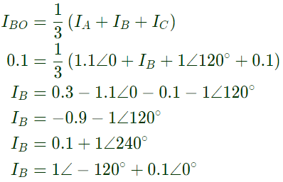
Q3: A 3-Bus network is shown. Consider generators as ideal voltage sources. If rows 1, 2 and 3 of the YBus matrix correspond to Bus 1, 2 and 3, respectively, then YBus of the network is (2021)
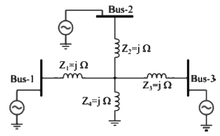 (a)
(a)  (b)
(b)  (c)
(c) 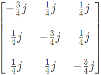 (d)
(d) 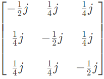 Ans: (c)
Sol: 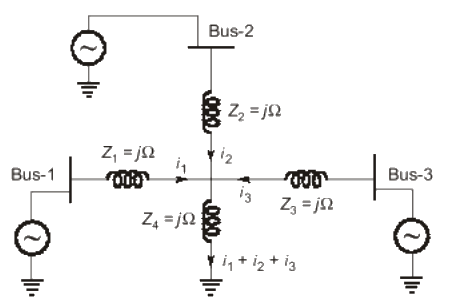

and V2 = ji1 + 2ji2 + ji3
V3 = ji1 + ji2 + 2ji3
∴ 
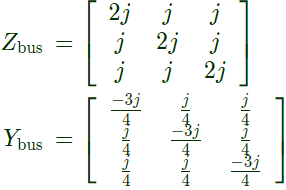
Q4: Consider a power system consisting of N number of buses. Buses in this power system are categorized into slack bus, PV buses and PQ buses for load flow study. The number of PQ buses is NL. The balanced Newton-Raphson method is used to carry out load flow study in polar form. H, S, M, and R are sub-matrices of the Jacobian matrix J as shown below:
 The dimension of the sub-matrix M is (2021)
(a) NL × (N−1)
(b) (N − 1) × (N − 1 − NL)
(c) NL × (N − 1 + NL)
(d) (N − 1) × (N − 1 + NL)
Ans: (a)
Sol:  For size of M
Row = No. of unknown variables of Q = NL
Column = No. of variable which has δ = NL+(N − 1 − NL)
= N − 1
So, size of M = NL × (N − 1)
Q5: Bus 1 with voltage magnitude V1 = 1.1p.u. is sending reactive power Q12 towards bus 2 with voltage magnitude V2 = 1p.u. through a lossless transmission line of reactance X. Keeping the voltage at bus 2 fixed at 1 p.u., magnitude of voltage at bus 1 is changed, so that the reactive power Q12 sent from bus 1 is increased by 20%. Real power flow through the line under both the conditions is zero. The new value of the voltage magnitude, V1, in p.u. (rounded off to 2 decimal places) at bus 1 is _______ . (2020)
 (a) 0.118
(b) 1.12
(c) 1
(d) 0.82
Ans: (b)
Sol: With real power zero, load angle δ = 0
with initial values, V1 = 1.1, V2 = 1

 With increased value of voltage,
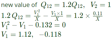 Hence the practical value in per unit V1 = 1.12 p.u.
Q6: Out of the following options, the most relevant information needed to specify the real power (P) at the PV buses in a load flow analysis is (2020)
(a) solution of economic load dispatc
(b) rated power output of the generator
(c) rated voltage of the generator
(d) base power of the generator
Ans: (a)
Sol: Most relevant information needed to specify P at PV buses is solution of economic load dispatch.
Q7: The Ybus matrix of a two-bus power system having two identical parallel lines connected between them in pu is given as
 The magnitude of the series reactance of each line in pu (round off up to one decimal place) is ______ (2019)
(a) 0.5
(b) 0.1
(c) 0.3
(d) 0.2
Ans: (b)
Sol: Y12 = −(y12) = −j20
Series admittance of each line
 Series reaactance of each line
Q8: The per-unit power output of a salient-pole generator which is connected to an infinite bus, is given by the expression, P = 1.4sinδ + 0.15sin2δ, where δ is the load angle. Newton-Raphson method is used to calculate the value of δ for P = 0.8 pu. If the initial guess is 30°, then its value (in degree) at the end of the first iteration is (2018)
(a) 15°
(b) 28.48°
(c) 28.74°
(d) 31.20°
Ans: (c)
Sol:  By using Newton Raphson method for single variable,


Q9: A 1000 x 1000 bus admittance matrix for an electric power system has 8000 non-zero elements. The minimum number of branches (transmission lines and transformers) in this system are _____ (up to 2 decimal places). (2018)
(a) 4000
(b) 6000
(c) 3500
(d) 7000
Ans: (c)
Sol: Number of buses = 1000
No. of non-zero element = 8000
% sparsity = %x
= Number of zero element/Total number of elements
((106) - 8000)/(106) = 0.992


Q10: In a load flow problem solved by Newton-Raphson method with polar coordinates, the size of the Jacobian is 100 x 100. If there are 20 PV buses in addition to PQ buses and a slack bus, the total number of buses in the system is ________. (SET-2(2017))
(a) 63
(b) 122
(c) 61
(d) 59
Ans: (c)
Sol: 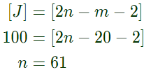 Total number of buses = n = 61.
Q11: The figure show the per-phase representation of a phase-shifting transformer connected between buses 1 and 2, where α is a complex number with non-zero real and imaginary parts.
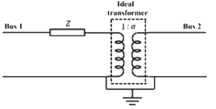 For the given circuit, Ybus and Zbus are bus admittance matrix and bus impedance matrix, respectively, each of size 2 x 2. Which one of the following statements is true? (SET-2(2017))
(a) Both Ybus and Zbus are symmetric
(b) Ybus is symmetric and bus Zbus is unsymmetric
(c) Ybus is unsymmetric and Zbus is symmetric
(d) Both Ybus and Zbus are unsymmetric
Ans: (d)
Sol: Both YBUS and ZBUS are unsymmetrical with transformer.
Q12: The bus admittance matrix for a power system network is
 There is a transmission line, connected between buses 1 and 3, which is represented by the circuit shown in figure.
 If this transmission line is removed from service, What is the modified bus admittance matrix? (SET-1(2017))
(a)  (b)
(b)  (c)
(c)  (d)
(d)  Ans: (c)
Sol: 
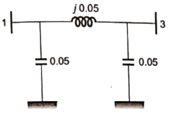 Reactance is eliminated in between Bus 1 and 3.
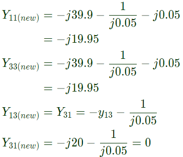 So, modified admittance matrix is,

Q13: A 10-bus power system consists of four generator buses indexed as G1, G2, G3, G4 and six load buses indexed as L1, L2, L3, L4, L5, L6. The generator bus G1 is considered as slack bus, and the load buses L3 and L4 are voltage controlled buses. The generator at bus G2 cannot supply the required reactive power demand, and hence it is operating at its maximum reactive power limit. The number of non-linear equations required for solving the load flow problem using Newton-Raphson method in polar form is _______. (SET-1 (2017))
(a) 18
(b) 20
(c) 14
(d) 10
Ans: (c)
Sol: Total number of buses ≡ 10
G1 ≡ slack bus
G2 ≡ PQ bus (reactive power limit is reached)
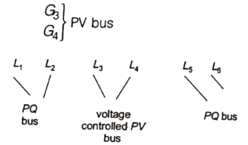 Minimum number of non linear equation to be sloved = Number of unknown bus voltage variables = (2 × 10 − 4 − 2) = 14
Q14: A 3-bus power system is shown in the figure below, where the diagonal elements of Y-bus matrix are Y11 = −j12pu, Y22 = −j15pu and Y33 = −j7pu
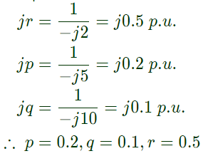
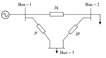 The per unit values of the line reactances p, q and r shown in the figure are (SET-1(2017))
(a) p = -0.2, q = -0.1, r = -0.5
(b) p = 0.2, q = 0.1, r = 0.5
(c) p = -5, q = -10, r = -2
(d) p = 5, q = 10, r = 2
Ans: (b)
Sol: Given,
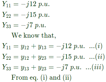
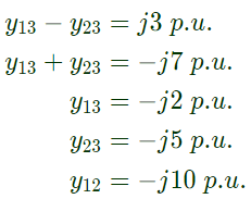 The p.u. values of line reactances p, q and r are
Q15: A power system has 100 buses including 10 generator buses. For the load flow analysis using Newton-Raphson method in polar coordinates, the size of the Jacobian is (SET-2 (2016))
(a) 189 x 189
(b) 100 x 100
(c) 90 x 90
(d) 180 x 180
Ans: (a)
Sol: Size of the Jacobian matrix is, (2n − m − 1) × (2n − m − 1)
Given that 10 generator buses, we need to assume with in the 10 buses one bus as slack bus the,
(2 × 100 − 10 − 1) × (2 × 100 − 10 − 1) = 189 × 189
Q16: In a 100 bus power system, there are 10 generators. In a particular iteration of Newton Raphson load flow technique (in polar coordinates), two of the PV buses are converted to PQ type. In this iteration, (SET-1(2016))
(a) the number of unknown voltage angles increases by two and the number of unknown voltage magnitudes increases by two.
(b) the number of unknown voltage angles remains unchanged and the number of unknown voltage magnitudes increases by two
(c) the number of unknown voltage angles increases by two and the number of unknown voltage magnitudes decreases by two.
(d) the number of unknown voltage angles remains unchanged and the number of unknown voltage magnitudes decreases by two.
Ans: (b)
Sol: The voltage angle is the commom variable for both PV and PQ buses si it remains unchanged. Where as voltage magnitude is specified in PV bus and not specified in PQ bus, so it increases by two.
Q17: A 3-bus power system network consists of 3 transmission lines. The bus admittance matrix of the uncompensated system is
 If the shunt capacitance of all transmission lines is 50% compensated, the imaginary part of the 3rd row 3rd column element (in pu) of the bus admittance matrix after compensation is (SET-2 (2015))
(a) -j7.0
(b) -j8.5
(c) -j7.5
(d) -j9.0
Ans: (b)
Sol:  By comparing for Y33 element
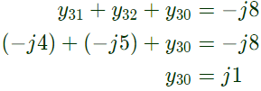 After compensating with 50% of shunt capacitance = j1 × 0.5 = j0.5
Hence, new value = −j8 − j0.5 = − j8.5
Q18: Determine the correctness or otherwise of the following Assertion [a] and the Reason [r].
Assertion: Fast decoupled load flow method gives approximate load flow solution because it uses several assumptions.
Reason: Accuracy depends on the power mismatch vector tolerance. (SET-1 (2015))
(a) Both [a] and [r] are true and [r] is the correct reason for [a].
(b) Both [a] and [r] are true but [r] is not the correct reason for [a].
(c) Both [a] and [r] are false.
(d) [a] is false and [r] is true.
Ans: (d)
Sol: FDLF method gives approximate solution not because it uses several assumption but due to the fixed number of iterations.
Q19: A 183 bus power system has 150 PQ buses and 32 PV buses. In the general case, to obtain the load flow solution using Newton-Raphson method in polar coordinates, the minimum number of simultaneous equations to be solved is _____. (SET-3 (2014))
(a) 150
(b) 224
(c) 332
(d) 468
Ans: (c)
Sol: 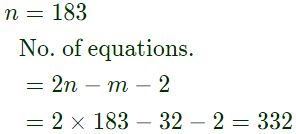 where,
n = Total number of buses
m = PV bus or reactive power support bus excluding slack bus
One bus already has taken as slack bus.
Q20: A two bus power system shown in the figure supplies load of 1.0 + j0.5 p.u.
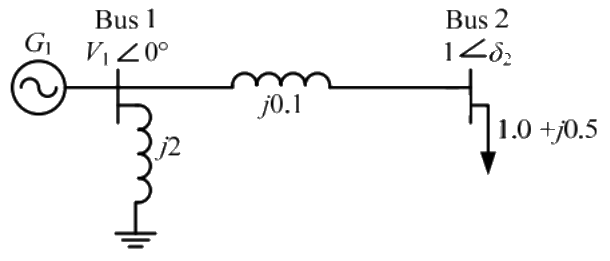 The values of V1 in p.u. and δ2 respectively are (SET-1(2014))
(a) 0.95 and 6.00°
(b) 1.05 and -5.44°
(c) 1.1 and -6.00°
(d) 1.1 and -27.12°
Ans: (b)
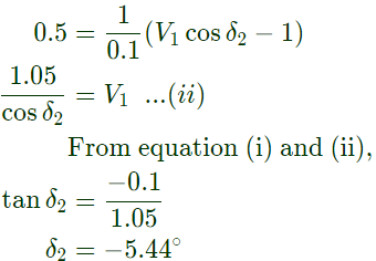
Sol: 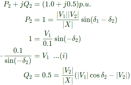

 where θ1 is the phase angle of the bus 1 voltage. The three buses can be categorized for load flow analysis as (2023)
 (a) Bus 1 Slack bus
 Now, from given power system network.
 (a)
(a)  (b)
(b)  (c)
(c)  (d)
(d)  Ans: (c)


 The dimension of the sub-matrix M is (2021)
 For size of M
 (a) 0.118
 With increased value of voltage,
 Hence the practical value in per unit V1 = 1.12 p.u.
  The magnitude of the series reactance of each line in pu (round off up to one decimal place) is ______ (2019)
 Series reaactance of each line
 By using Newton Raphson method for single variable,


 Total number of buses = n = 61.
 For the given circuit, Ybus and Zbus are bus admittance matrix and bus impedance matrix, respectively, each of size 2 x 2. Which one of the following statements is true? (SET-2(2017))
 There is a transmission line, connected between buses 1 and 3, which is represented by the circuit shown in figure.
 If this transmission line is removed from service, What is the modified bus admittance matrix? (SET-1(2017))
 (b)
(b)  (c)
(c)  (d)
(d)  Ans: (c)
 Reactance is eliminated in between Bus 1 and 3.
 So, modified admittance matrix is,
 Minimum number of non linear equation to be sloved = Number of unknown bus voltage variables = (2 × 10 − 4 − 2) = 14
 The per unit values of the line reactances p, q and r shown in the figure are (SET-1(2017))
 The p.u. values of line reactances p, q and r are
 If the shunt capacitance of all transmission lines is 50% compensated, the imaginary part of the 3rd row 3rd column element (in pu) of the bus admittance matrix after compensation is (SET-2 (2015))
 By comparing for Y33 element
 After compensating with 50% of shunt capacitance = j1 × 0.5 = j0.5
 where,
 The values of V1 in p.u. and δ2 respectively are (SET-1(2014))


