Electrical Engineering (EE) Exam  >  Electrical Engineering (EE) Notes  >  Analog and Digital Electronics  >  Previous Year Questions- Logic Gates

Previous Year Questions- Logic Gates | Analog and Digital Electronics - Electrical Engineering (EE) PDF Download

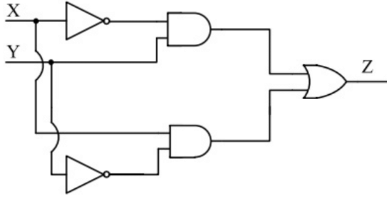
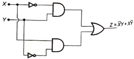
Q1: In the circuit shown below, X and Y are digital inputs, and Z is a digital output. The equivalent circuit is a (2019)
Previous Year Questions- Logic Gates | Analog and Digital Electronics - Electrical Engineering (EE)(a) NAND gate
(b) NOR gate
(c) XOR gate
(d) XNOR gate
Ans:
(c)
Sol: The Boolean expression for the output of the digital circuit is shown below
Previous Year Questions- Logic Gates | Analog and Digital Electronics - Electrical Engineering (EE)The above expression is of XOR gate.

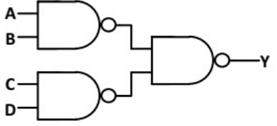
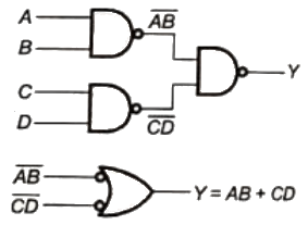
Q2: In the logic circuit shown in the figure, Y is given by (2018)
Previous Year Questions- Logic Gates | Analog and Digital Electronics - Electrical Engineering (EE) (a) Y = ABCD
(b) Y = (A + B)(C + D)
(c) Y = A + B + C + D
(d) Y = AB + CD
Ans:
(d)
Sol: Previous Year Questions- Logic Gates | Analog and Digital Electronics - Electrical Engineering (EE)
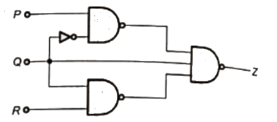
Q3: For a 3-input logic circuit shown below, the output Z can be expressed as (SET-2 (2017))
Previous Year Questions- Logic Gates | Analog and Digital Electronics - Electrical Engineering (EE)(a) Previous Year Questions- Logic Gates | Analog and Digital Electronics - Electrical Engineering (EE)

(b) Previous Year Questions- Logic Gates | Analog and Digital Electronics - Electrical Engineering (EE)
(c) Previous Year Questions- Logic Gates | Analog and Digital Electronics - Electrical Engineering (EE)
(d) Previous Year Questions- Logic Gates | Analog and Digital Electronics - Electrical Engineering (EE)
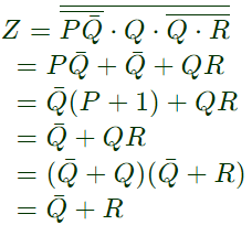
Ans: (c)
SolPrevious Year Questions- Logic Gates | Analog and Digital Electronics - Electrical Engineering (EE)Previous Year Questions- Logic Gates | Analog and Digital Electronics - Electrical Engineering (EE)
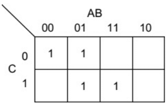
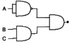
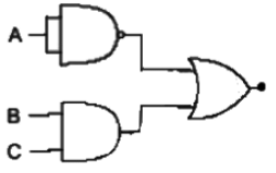
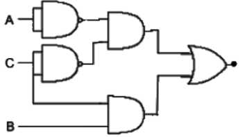
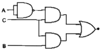
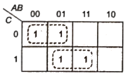
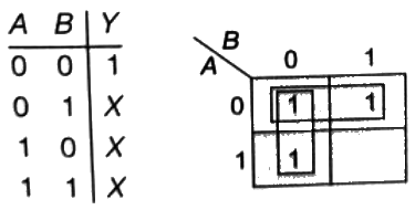
Q4: Which of the following logic circuits is a realization of the function F whose Karnaugh map is shown in figure (SET-1 (2014))
Previous Year Questions- Logic Gates | Analog and Digital Electronics - Electrical Engineering (EE)(a) Previous Year Questions- Logic Gates | Analog and Digital Electronics - Electrical Engineering (EE)(b) Previous Year Questions- Logic Gates | Analog and Digital Electronics - Electrical Engineering (EE)(c) Previous Year Questions- Logic Gates | Analog and Digital Electronics - Electrical Engineering (EE)(d) Previous Year Questions- Logic Gates | Analog and Digital Electronics - Electrical Engineering (EE)Ans: 
(c)
Sol: Previous Year Questions- Logic Gates | Analog and Digital Electronics - Electrical Engineering (EE)Previous Year Questions- Logic Gates | Analog and Digital Electronics - Electrical Engineering (EE)
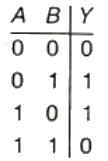
Q5: A bulb in a staircase has two switches, one switch being at the ground floor and the other one at the first floor. The bulb can be turned ON and also can be turned OFF by any one of the switches irrespective of the state of the other switch. The logic of switching of the bulb resembles (2013)
(a) and AND gate
(b) an OR gate
(c) an XOR gate
(d) a NAND gate
Ans: 
(c)
Sol: Truth table of XOR gate is,
Previous Year Questions- Logic Gates | Analog and Digital Electronics - Electrical Engineering (EE)So, from the XOR gate truth table, it is clear that the bulb can be turned ON and also can be turned OFF by any one of the switched irrespective of the state of the other switch.

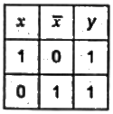
Q6: The output Y of the logic circuit given below is (2011)
Previous Year Questions- Logic Gates | Analog and Digital Electronics - Electrical Engineering (EE)(a) 1
(b) 0
(c) x
(d) Previous Year Questions- Logic Gates | Analog and Digital Electronics - Electrical Engineering (EE)

Ans: (a)
Sol: Previous Year Questions- Logic Gates | Analog and Digital Electronics - Electrical Engineering (EE)Previous Year Questions- Logic Gates | Analog and Digital Electronics - Electrical Engineering (EE)
Q7: The complete set of only those Logic Gates designated as Universal Gates is (2009)
(a) NOT, OR and AND Gates
(b) XNOR, NOR and NAND Gates
(c) NOR and NAND Gates
(d) XOR, NOR and NAND Gates
Ans:
(c)
Sol: NOR and NAND are designated as universal logic gates because using any one of them, we can omplement all the logic gates.

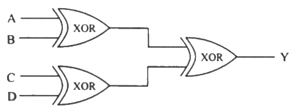
Q8: A, B, C and D are input, and Y is the output bit in the XOR gate circuit of the figure below. Which of the following statements about the sum S of A, B, C, D and Y is correct ? (2007)
Previous Year Questions- Logic Gates | Analog and Digital Electronics - Electrical Engineering (EE)(a) S is always with zero or odd
(b) S is always either zero or even
(c) S = 1 only if the sum of A,B,C and D is even
(d) S = 1 only if the sum of A,B,C and D is odd
Ans:
(b)
Sol: Y = A ⊕ B ⊕ C ⊕ D from the given diagram
we know that sum of anu no. of bits is XOR of all bits.
So, S = A ⊕ B ⊕ C ⊕ D ⊕ Y
S = Y ⊕ Y
S = either zero or even because LSB is zero (always)

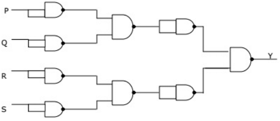
Q9: For the circuit shown in figure, the Boolean expression for the output Y in terms of inputs P, Q, R and S is (2002)
Previous Year Questions- Logic Gates | Analog and Digital Electronics - Electrical Engineering (EE)(a) Previous Year Questions- Logic Gates | Analog and Digital Electronics - Electrical Engineering (EE)

(b) P + Q + R + S
(c) Previous Year Questions- Logic Gates | Analog and Digital Electronics - Electrical Engineering (EE)

(d) (P+Q)(R+S)(P + Q)(R + S)
Ans:
(b)
Sol: Previous Year Questions- Logic Gates | Analog and Digital Electronics - Electrical Engineering (EE)⇒ Y = (P + Q + R + S)

Q10: The output of a logic gate is "1" when all its inputs are at logic "0". The gate is either (2001)
(a) a NAND or an EX-OR gate
(b) a NOR or an EX-OR gate
(c) an AND or an EX-NOR gate
(d) a NOR or an EX-NOR gate
Ans:
(d)
Sol: Previous Year Questions- Logic Gates | Analog and Digital Electronics - Electrical Engineering (EE)Previous Year Questions- Logic Gates | Analog and Digital Electronics - Electrical Engineering (EE)

The document Previous Year Questions- Logic Gates | Analog and Digital Electronics - Electrical Engineering (EE) is a part of the Electrical Engineering (EE) Course Analog and Digital Electronics.
All you need of Electrical Engineering (EE) at this link: Electrical Engineering (EE)
137 videos|143 docs|71 tests

Top Courses for Electrical Engineering (EE)

FAQs on Previous Year Questions- Logic Gates - Analog and Digital Electronics - Electrical Engineering (EE)

1. What are the basic types of logic gates used in electrical engineering?
Ans.The basic types of logic gates used in electrical engineering include AND, OR, NOT, NAND, NOR, XOR, and XNOR gates. Each gate performs a specific logical function that can be represented in truth tables.
2. How do logic gates work in digital circuits?
Ans.Logic gates work by taking one or more binary inputs and producing a single binary output based on the type of gate and the input values. For instance, an AND gate outputs a high signal (1) only when all its inputs are high.
3. What is the significance of truth tables in understanding logic gates?
Ans.Truth tables are significant as they provide a clear representation of how a logic gate operates under different input conditions. They list all possible input combinations and the corresponding output, making it easier to analyze and design digital circuits.
4. How can logic gates be combined to create complex circuits?
Ans.Logic gates can be combined in various configurations (series and parallel) to create complex circuits such as adders, multiplexers, and flip-flops. By interconnecting gates, engineers can design circuits that perform more intricate operations than a single gate.
5. What role do logic gates play in modern digital devices?
Ans.Logic gates are fundamental components of modern digital devices, as they are used in microprocessors, memory devices, and various digital systems. They enable the processing of binary data, which is essential for computing and communication technologies.
137 videos|143 docs|71 tests
Download as PDF
Explore Courses for Electrical Engineering (EE) exam

Top Courses for Electrical Engineering (EE)

Signup for Free!
Signup to see your scores go up within 7 days! Learn & Practice with 1000+ FREE Notes, Videos & Tests.
10M+ students study on EduRev
Related Searches

pdf

,

Semester Notes

,

past year papers

,

practice quizzes

,

Previous Year Questions- Logic Gates | Analog and Digital Electronics - Electrical Engineering (EE)

,

Previous Year Questions- Logic Gates | Analog and Digital Electronics - Electrical Engineering (EE)

,

shortcuts and tricks

,

Exam

,

Viva Questions

,

Summary

,

MCQs

,

mock tests for examination

,

ppt

,

study material

,

Free

,

video lectures

,

Sample Paper

,

Previous Year Questions with Solutions

,

Important questions

,

Previous Year Questions- Logic Gates | Analog and Digital Electronics - Electrical Engineering (EE)

,

Extra Questions

,

Objective type Questions

;