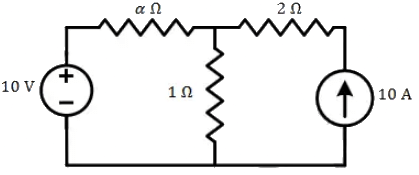
Q1: All the elements in the circuit are ideal. The power delivered by the 10 V source in watts is (2024)
 (a) 0
(a) 0
(b) 50
(c) 100
(d) dependent on the value of α
Ans: (a)
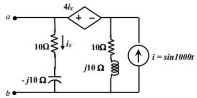
Q2: For the circuit shown, if i = sin 1000t, the instantaneous value of the Thevenin's equivalent voltage (in Volts) across the terminals a-b at time t = 5 ms is ___ (Round off to 2 decimal places). (2023)
 (a) -12.25
(b) 12.25
(c) 11.97
(d) -11.97
Ans: (d)
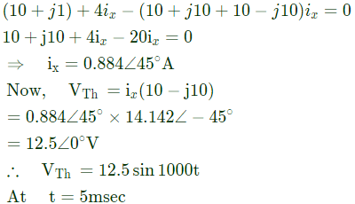
Sol: By source transformation, the circuit become
 Apply KVL in loop,

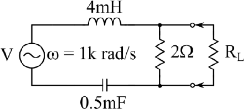
Q3: In the given circuit, for maximum power to be delivered to RL, its value should be ______________ Ω.
(Round off to 2 decimal places.) (2021)
 (a) 2.14
(b) 3.32
(c) 1.42
(d) 4.12
Ans: (c)
Sol: 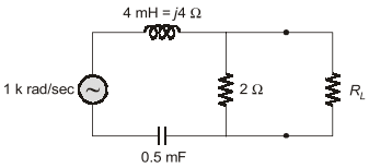

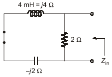
 For maximum power transfer,

Q4: A signal generator having a source resistance of 50Ω is set to generate a 1 kHz sinewave. Open circuit terminal voltage is 10 V peak-to-peak. Connecting a capacitor across the terminals reduces the voltage to 8 V peak-to-peak. The value of this capacitor is _______ μF. (Round off to 2 decimal places.) (2021)
(a) 4.25
(b) 6.32
(c) 1.25
(d) 2.38
Ans: (d)
Sol: 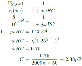
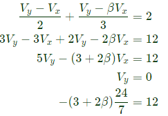
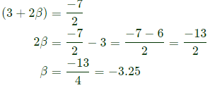
Q5: In the given circuit, for voltage Vy to be zero, the value of β should be _________. (Round off to 2 decimal places). (2021)
 (a) -4.58
(b) -3.25
(c) 4.65
(d) 3.45
Ans: (b)
Sol: 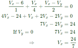
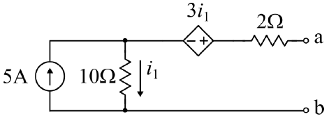
Q6: For the network shown, the equivalent Thevenin voltage and Thevenin impedance as seen across terminals 'ab' is (2021)
(a) 10 V in series with 12Ω
(b) 65 V in series with 15Ω
(c) 50 V in series with 2Ω
(d) 35 V in series with 2Ω
Ans: (b)
Sol: Given circuit can be resolved as shown below,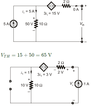

Q7: A benchtop dc power supply acts as an ideal 4 A current source as long as its terminal voltage is below 10 V. Beyond this point, it begins to behave as an ideal 10 V voltage source for all load currents going down to 0 A. When connected to an ideal rheostat, find the load resistance value at which maximum power is transferred, and the corresponding load voltage and current. (2020)
(a) Short, ∞ A, 10 V
(b) Open, 4 A, 0 V
(c) 2.5 Ω, 4 A, 10 V
(d) 2.5 Ω, 4 A, 5 V
Ans: (c)
Sol: 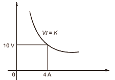 Maximum power transistor of VI product is maximum. If draw the the curve, it intersect (10, 4) that will give maximum power. The terminal voltage is 10 V (Load voltage) and current is 4 A (Load current). Load resistance is 10/4 = 2.5Ω.
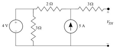
Q8: The Thevenin equivalent voltage, VTH, in V (rounded off to 2 decimal places) of the network shown below, is _______ . (2020)
 (a) 5
(a) 5
(b) 7
(c) 14
(d) 6
Ans: (c)
Sol: Only voltage source 4V is there and current source 5A is open circuited
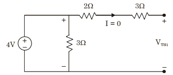 From the above circuit,
VTH1 = 4V
Case-II:
Only current source 5A is there and voltage source 4V is short circuited.
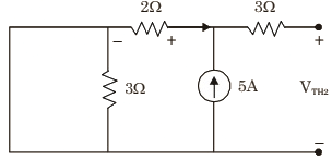 From the above circuit,
VTH2 = 2 × 5 = 10V
By applying superposition theorem,
VTH = VTH1 + VTH2 = 10 + 4 = 14V
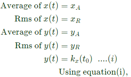
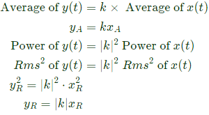
Q9: xR and xA are, respectively, the rms and average values of x(t) = x(t − T), and similarly, yR and yA are, respectively, the rms and average values of y(t) = kx(t).k, T are independent of t. Which of the following is true? (2020)
(a) yA = kxA;yR = kxR
(b) yA = kxA; yR ≠ kxR
(c) yA ≠ kxA;yR = kxR
(d) yA ≠ kxA;yR ≠ kxR
Ans: (a)
Sol: Given that,

Q10: The current flowing in the circuit shown below in amperes is _____ (2019)
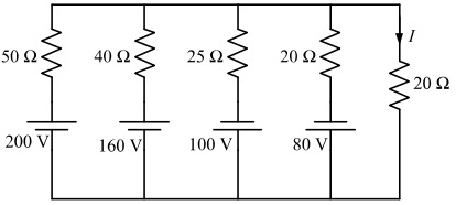 (a) 0
(a) 0
(b) 1
(c) 2
(d) 4
Ans: (a)
Sol: 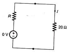 By Millman'e theorem,
 Simplified circuit,
∴ I = 0A
Q11: In the circuit shown below, the value of capacitor C required for maximum power to be transferred to the load is (SET-2 (2017))
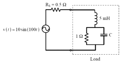 (a) 1nF
(b) 1 μF
(c) 1mF
(d) 10mF
Ans: (d)
Sol: 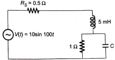 The frequency at which the load is resistive and it is equal to 0.5Ω i.e. The load is resistive means, the imaginary part of load is equal to zero and real part is equal to 0.5Ω.
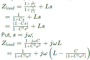 Real part of the

Q12: For the network given in figure below, the Thevenin's voltage Vab is (SET-2 (2017))
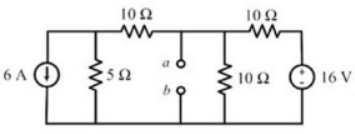 (a) -1.5 V
(b) - 0.5 V
(c) 0.5 V
(d) 1.5 V
Ans: (a)
Sol: Consider the following circuit,
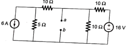 After rearrangement, we get,
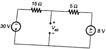 From circuit using KCL,

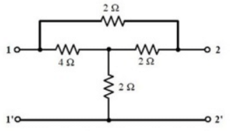
Q13: For the given 2-port network, the value of transfer impedance Z21 in ohms is_______ (SET-2 (2017))
 (a) 1
(a) 1
(b) 2
(c) 3
(d) 4
Ans: (c)
Sol: 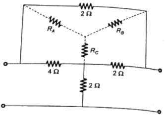 Where, RA= 1Ω
 After rearrangement consider the following circuit,
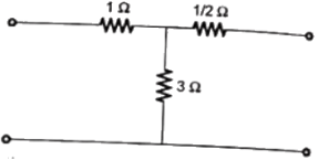 From the circuit diagram, we get,
Z21 = V2/V1 = 3Ω
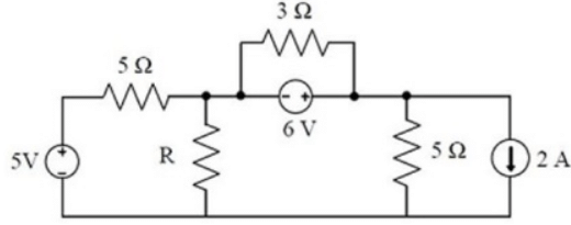
Q14: In the circuit shown below, the maximum power transferred to the resistor R is _______ W. (SET-1 (2017))
 (a) 2.5
(b) 1.5
(c) 6
(d) 3
Ans: (d)
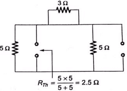
Sol: To get Rth and Vth, consider the following steps.
Case-1: For Rth
 For Vth
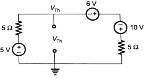 Applying KCL at node,
 Maximum power transferred,

Q15: In a linear two-port network, when 10 V is applied to Port 1, a current of 4 A flows through Port 2 when it is short-circuited. When 5 V is applied to Port 1, a current of 1.25 A flows through a 1 Ω resistance connected across Port 2. When 3 V is applied to Port 1, the current (in Ampere) through a 2 Ω resistance connected across Port 2 is _______. (SET-1 (2015))
(a) 0.225
(b) 0.545
(c) 0.845
(d) 1.475
Ans: (b)
Sol: 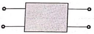
 as we know from ABCD parameter,
 From condition (i),
 From condition (ii),
 From condition (iii),

Q16: The circuit s hown in the figure has two sources connected in series. The instantaneous voltage of the AC source (in Volt) is given by v(t) = 12sint. If the circuit is in steady state, then the rms value of the current (in Ampere) flowing in the circuit is ______ . (SET-1 (2015))
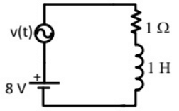 (a) 7
(a) 7
(b) 10
(c) 15
(d) 14
Ans: (b)
Sol: 
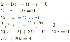
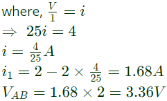
Q17: For the given circuit, the Thevenin equivalent is to be determined. The Thevenin voltage, VTh (in Volt), seen from terminal AB is __________. (SET-1 (2015))
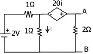 (a) 1.28
(b) 2.42
(c) 3.36
(d) 5.25
Ans: (c)
Sol: 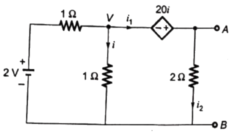
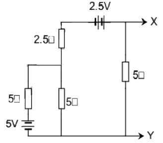
Q18: The Norton's equivalent source in amperes as seen into terminals X and Y is ____. (SET-3 (2014))
 (a) 1
(a) 1
(b) 2
(c) 3
(d) 4
Ans: (b)
Sol: Using source transformation theoram,
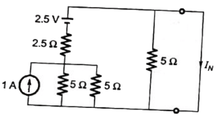 or we can simplify the network,
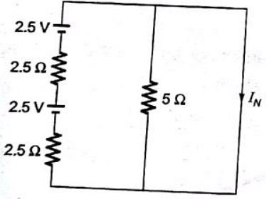 Now, from the circuit, we get,
IN = 5/5 = 1A
Q19: A non-ideal voltage source Vs has an internal impedance of Zs. If a purely resistive load is to be chosen that maximizes the power transferred to the load, its value must be (SET-3 (2014))
(a) 0
(b) real part of Zs
(c) magnitude of Zs
(d) complex conjugate of Zs
Ans: (c)
Sol: Thesituation of problem is shown in figure:
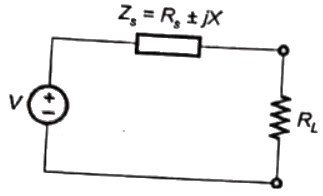 For the transfer of maximum power from source to load,

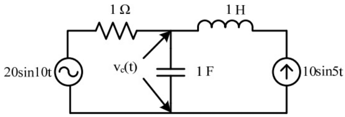
Q20: The voltage across the capacitor, as shown in the figure, is expressed as  The values of A1 and A2 respectively, are (SET-2 (2014))
 (a) 2.0 and 1.98
(b) 2.0 and 4.20
(c) 2.5 and 3.50
(d) 5.0 and 6.40
Ans: (a)
Sol: Let us apply superposition theorem,
Consider the voltage source 20sint alone
Then, 10sin5t remain open circuited.
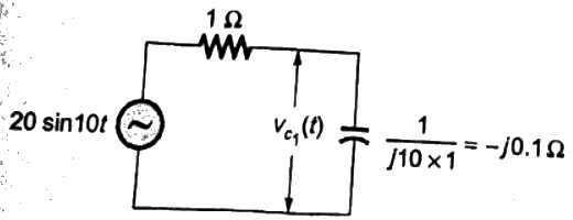 Let, Vc1(t) be the voltage across capacitor
 Considering the current source 10 sin 5t alone.
Then, 20 sin 10t voltage source remain short circuited
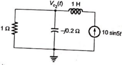 Let voltage across capacitor = Vc2 (t)
 Using superposition theoram, voltage across capacitor is
 Comparing equation (iii) and (iv), we have
A = 2 and B = 1.97 ≈ 1.98
 (a) 0
(a) 0 (a) -12.25
 Apply KVL in loop,

 (a) 2.14


 For maximum power transfer,

 (a) -4.58


 Maximum power transistor of VI product is maximum. If draw the the curve, it intersect (10, 4) that will give maximum power. The terminal voltage is 10 V (Load voltage) and current is 4 A (Load current). Load resistance is 10/4 = 2.5Ω.
 (a) 5
(a) 5 From the above circuit,
 From the above circuit,


 (a) 0
(a) 0 By Millman'e theorem,
 Simplified circuit,
 (a) 1nF
 The frequency at which the load is resistive and it is equal to 0.5Ω i.e. The load is resistive means, the imaginary part of load is equal to zero and real part is equal to 0.5Ω.
 Real part of the
 (a) -1.5 V
 After rearrangement, we get,
 From circuit using KCL,
 (a) 1
(a) 1 Where, RA= 1Ω
 After rearrangement consider the following circuit,
 From the circuit diagram, we get,
 (a) 2.5
 For Vth
 Applying KCL at node,
 Maximum power transferred,

 as we know from ABCD parameter,
 From condition (i),
 From condition (ii),
 From condition (iii),
 (a) 7
(a) 7
 (a) 1.28


 (a) 1
(a) 1 or we can simplify the network,
 Now, from the circuit, we get,
 For the transfer of maximum power from source to load,
 The values of A1 and A2 respectively, are (SET-2 (2014))
 (a) 2.0 and 1.98
 Let, Vc1(t) be the voltage across capacitor
 Considering the current source 10 sin 5t alone.
  Let voltage across capacitor = Vc2 (t)
 Using superposition theoram, voltage across capacitor is
 Comparing equation (iii) and (iv), we have


