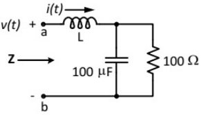
Q1: The voltage v(t) across the terminals a and b as shown in the figure, is a sinusoidal voltage having a frequency ω = 100 radian/s. When the inductor current i(t) is in phase with the voltage v(t), the magnitude of the impedance Z (in Ω) seen between the terminals a and b is ________ (up to 2 decimal places). (2018)
 (a) 25
(b) 50
(c) 100
(d) 150
Ans: (b)
Sol: At resonance imaginary part of Zeq = 0

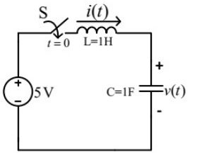
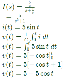
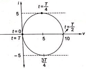
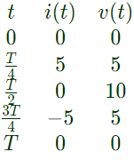
Q2: A DC voltage source is connected to a series L-C circuit by turning on the switch S at time t = 0 as shown in the figure. Assume i(0) = 0, v(0) = 0. Which one of the following circular loci represents the plot of i(t) versus v(t) ? (2018)
 (a)
(a)  (b)
(b)  (c)
(c) 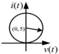
(d) 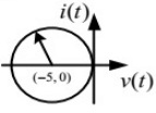 Ans: (b)
Sol: 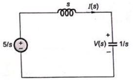
Q3: In the balanced 3-phase, 50 Hz, circuit shown below, the value of inductance (L) is 10 mH. The value of the capacitance (C) for which all the line currents are zero, in millifarads, is ___________. (SET-2 (2016))
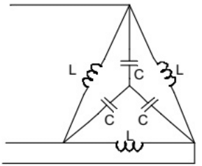 (a) 1.32
(b) 2.12
(c) 3.03
(d) 4.08
Ans: (c)
Sol: Usingstar to delta conversion,
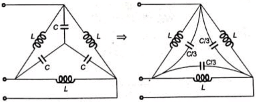 Line current will be zero when the parallel pair of induction capacitor is resonant at f = 50Hz
 Since, L = 10mH
C will be 3.03 mF.
Q4: The circuit below is excited by a sinusoidal source. The value of R, in Ω, for which the admittance of the circuit becomes a pure conductance at all frequencies is _____________. (SET-1 (2016))
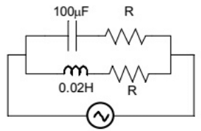 (a) 14.14
(b) 8.62
(c) 22.46
(d) 12.18
Ans: (a)
Sol: The resonant frequency for the circuit is
 So the circuit will have zero real part of admittance when,

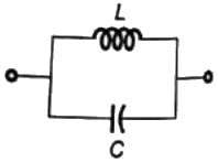
Q5: An inductor is connected in parallel with a capacitor as shown in the figure.
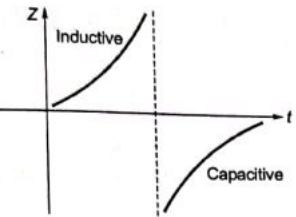
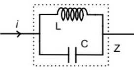 As the frequency of current i is increased, the impedance (Z) of the network varies as (SET-1 (2015))
(a) 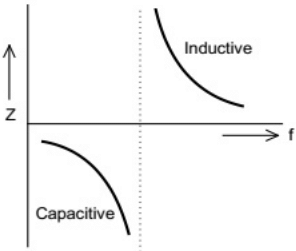 (b)
(b) 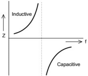 (c)
(c) 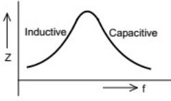 (d)
(d) 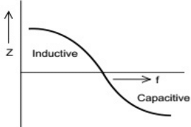 Ans: (b)
Sol: 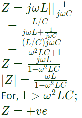

Q6: A series RLC circuit is observed at two frequencies. At ω1 = 1 krad/s, we note that source voltage V1 = 100∠0° V results in a current I1 = 0.03∠31°A. At ω2 = 2 krad/s, the source voltage V2 = 100∠0° V results in a current I2 = 2∠0∘. The closest values for R, L, C out of the following options are (SET-3 (2014))
(a) R = 50 Ω ; L = 25mH; C = 10 μ F;
(b) R = 50 Ω ; L = 10 mH; C = 25 μ F;
(c) R = 50 Ω ; L = 50 mH; C = 5 μ F;
(d) R = 50 Ω ; L = 5mH; C = 50 μ F;
Ans: (b)
Sol: Given
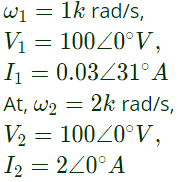
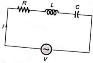 At ω2 = 2k rad/s, voltage and current are in phase. Thus, it is a case of series resonance,
 ∴ Resistance of circuit,
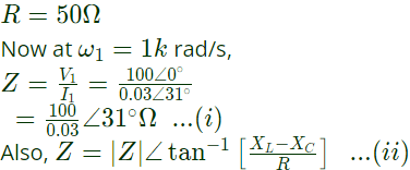 Comparing equation (i) and (ii), we have:
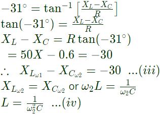 From equation (iii),
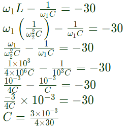 Substituting the value of C in equation (iv), we get,
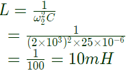 Therefore, values are:
R = 50Ω,
L=10mH,
C = 25μF
Q7: Two magnetically uncoupled inductive coils have Q factors q1 and q2 at the chosen operating frequency. Their respective resistances are R1 and R2. When connected in series, their effective Q factor at the same operating frequency is (2013)
(a) q1R1 + q2R2
(b) (q1/R1) + (q2/R2)
(c) (q1R1 + q2R2)/(R1 + R2)
(d) q1R2 + q2R1
Ans: (c)
Sol: 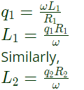

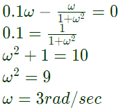
Q8: The resonant frequency for the given circuit will be (2008)
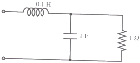 (a) 1 rad/s
(b) 2 rad/s
(c) 3 rad/s
(d) 4 rad/s
Ans: (c)
Sol: Input impedance

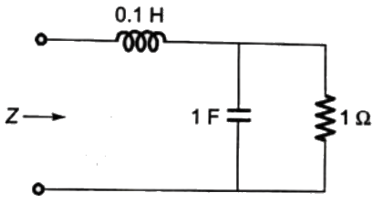
 At resonance, imaginary part must be zero.
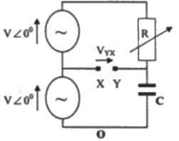
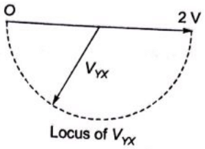
Q9: In the figure given below all phasors are with reference to the potential at point "O". The locus of voltage phasor VXY as R is varied from zero to infinity is shown by (2007)
 (a)
(a) 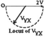 (b)
(b) 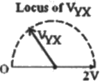 (c)
(c) 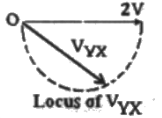 (d)
(d) 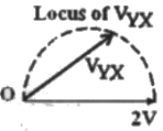 Ans: (a)
Sol: 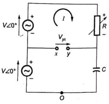 Let, capacitive reactance = XC
 Using KVL,
 Method-1:
 When R = 0
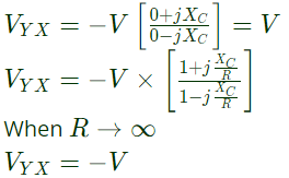 Method-2:
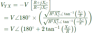 Magnitude of VYX = V
So, option (C) and (D) can not be correct, as magnitude is 2 V in these two options.
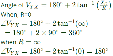 on the basis of above analysis, the locus of VYX is drawn below:
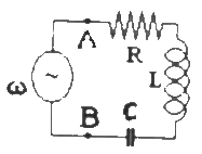
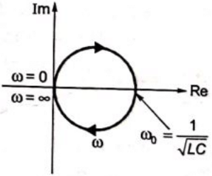
Q10: The R-L-C series circuit shown in figure is supplied from a variable frequency voltage source. The admittance-locus of the R-L-C network at terminals AB for increasing frequency ω is (2007)
 (a)
(a) 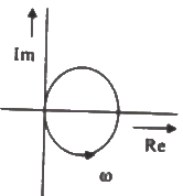 (b)
(b) 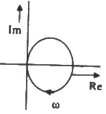 (c)
(c) 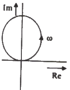 (d)
(d) 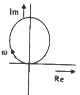 Ans: (d)
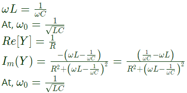
Sol: Admittance of the series connected RLC
 Separating, real and imaginary part of admittance.
 For any value of ω , the real part is always positive. When,
 Imaginary part of zero
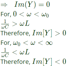 On the basis of above analysis, the admittance locus is
Q11:The circuit shown in the figure is energized by a sinusoidal voltage source V1 at a frequency which causes resonance with a current of I.
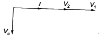
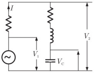 The phasor diagram which is applicable to this circuit is (2006)
(a) 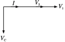 (b)
(b) 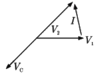 (c)
(c) 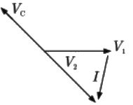 (d)
(d) 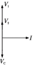 Ans: (a)
Sol: 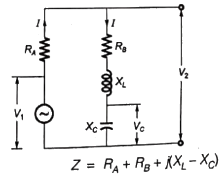 At resonance,
 Therefore, input impedance in purely resistive, is minimum, and the input voltage and output current are in phase.
So, V1 and I are in phase
 But, XL = XC
 Therefore, V2 is in phase with V1 and V2 < V1 voltage across the capacitor
 So, VC lags the current by 90∘.
The phasor diagram on the basis of above analysis.
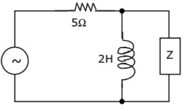
Q12: The value of Z in figure, which is most appropriate to cause parallel resonance at 500 Hz is (2004)
 (a) 125.00 mH
(b)304.20 μF
(c) 2.0 μF
(d) 0.05 μF
Ans: (d)
Sol: Atresonance, the circuit should be in unity power factor.
Hence, 'Z' should be capacitive.
Admittance of the parallel circuit.

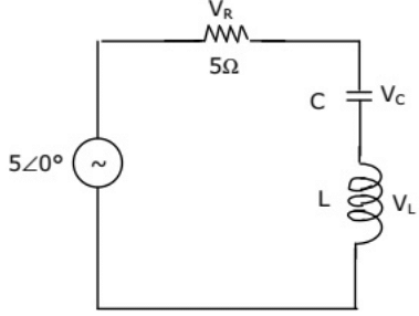
Q13: In the circuit of figure, the magnitudes of VL and VC are twice that of VR. Given that f = 50 Hz, the inductance of the coil is (2003)
 (a) 2.14 mH
(b) 5.30 H
(c) 31.8 mH
(d) 1.32 H
Ans: (c)
Sol:  Therefore, the circuit is at resonance and
VR = V
Quality factor  As we know,

Q14: A series R-L-C circuit has R = 50Ω, L = 100μ and C = 1μ. The lower half power frequency of the circuit is (2002)
(a) 30.55 kHz
(b) 3.055 kHz
(c) 51.92 kHz
(d) 1.92 kHz
Ans: (b)
Sol: 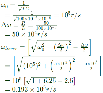

Q15: In the circuit shown in figure, what value of C will cause a unity power factor at the ac source? (2002)
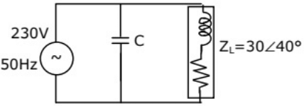 (a) 68.1 μF
(b) 165 μF
(c) 0.681 μF
(d) 6.81 μF
Ans: (a)
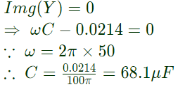
Sol: 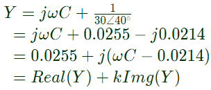 To have unity power factor at ac source i.e. resonance condition,
Q16: In a series RLC circuit at resonance, the magnitude of the voltage developed across the capacitor (2001)
(a) is always zero
(b) can never be greater than the input voltage
(c) can be greater than the input voltage, however, it is 90∘ out of phase with the input voltage
(d) can be greater than the input voltage, and is in phase with the input voltage.
Ans: (c)
Sol: In a series RLC circuit, at resonance
 Hence, option (C) is correct.
 (a) 25
 (a)
(a)  (b)
(b)  (c)
(c) 
 Ans: (b)


 (a) 1.32
 Line current will be zero when the parallel pair of induction capacitor is resonant at f = 50Hz
 Since, L = 10mH
 (a) 14.14
 So the circuit will have zero real part of admittance when,
 As the frequency of current i is increased, the impedance (Z) of the network varies as (SET-1 (2015))
 (b)
(b)  (c)
(c)  (d)
(d)  Ans: (b)


 At ω2 = 2k rad/s, voltage and current are in phase. Thus, it is a case of series resonance,
 ∴ Resistance of circuit,
 Comparing equation (i) and (ii), we have:
 From equation (iii),
 Substituting the value of C in equation (iv), we get,
 Therefore, values are:

 (a) 1 rad/s

 At resonance, imaginary part must be zero.
 (a)
(a)  (b)
(b)  (c)
(c)  (d)
(d)  Ans: (a)
 Let, capacitive reactance = XC
 Using KVL,
 Method-1:
 When R = 0
 Method-2:
 Magnitude of VYX = V
 on the basis of above analysis, the locus of VYX is drawn below:
 (a)
(a)  (b)
(b)  (c)
(c)  (d)
(d)  Ans: (d)
 Separating, real and imaginary part of admittance.
 For any value of ω , the real part is always positive. When,
 Imaginary part of zero
 On the basis of above analysis, the admittance locus is
 The phasor diagram which is applicable to this circuit is (2006)
 (b)
(b)  (c)
(c)  (d)
(d)  Ans: (a)
 At resonance,
 Therefore, input impedance in purely resistive, is minimum, and the input voltage and output current are in phase.
 But, XL = XC
 Therefore, V2 is in phase with V1 and V2 < V1 voltage across the capacitor
 So, VC lags the current by 90∘.
 (a) 125.00 mH
 (a) 2.14 mH
 Therefore, the circuit is at resonance and
 As we know,


 (a) 68.1 μF
 To have unity power factor at ac source i.e. resonance condition,
 Hence, option (C) is correct.


