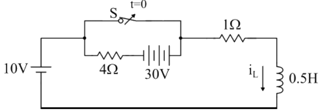
Q1: The circuit shown in the figure with the switch S open, is in steady state. After the switch S is closed, the time constant of the circuit in seconds is (2024)
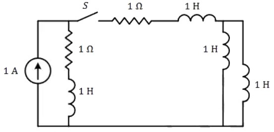 (a) 1.25
(b) 0
(c) 1
(d) 1.5
Ans: (a)
Sol: 
Q2: The circuit shown in the figure is initially in the steady state with the switch K in open condition and  in closed condition. The switch K is closed and
  is opened simultaneously at the instant t = t1, where t1 > 0. The minimum value of t1 in milliseconds, such that there is no transient in the voltage across the 100μF capacitor, is ___ (Round off to 2 decimal places). (2023)
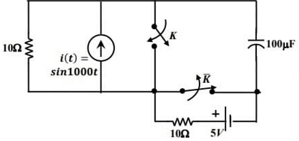 (a) 0.87
(b) 1.57
(c) 1.88
(d) 2.26
Ans: (b)
Sol: Switch K is open and  is closed.
Redraw the circuit :
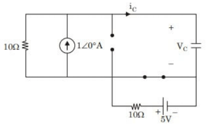 From circuit, using current division,

 Case (ii) :
Switch K is closed and is open.
Current source and 10Ω resistor becomes short circuited.
Redraw the circuit :
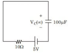 From circuit,

 We have,
 For transient free voltage,


Q3: In the circuit shown below, the switch S is closed at t = 0. The magnitude of the steady state voltage, in volts, across the 6Ω resistor is _________. (round off to two decimal places). (2022)
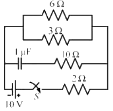 (a) 5
(a) 5
(b) 8.25
(c) 12.55
(d) 3.35
Ans: (a)
Sol: Concept: At steady state, capacitor behaves as open circuit.
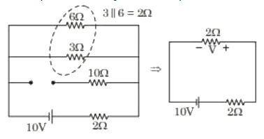 Using voltage division,

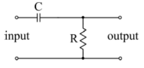
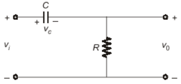
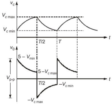
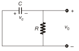
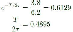
Q4: A 100 Hz square wave, switching between 0 V and 5 V, is applied to a CR high-pass filter circuit as shown. The output voltage waveform across the resistor is 6.2 V peak-to-peak. If the resistance R is 820 Ω, then the value C is ______________ μF. (Round off to 2 decimal places.) (2021)
 (a) 18.5
(b) 12.46
(c) 10.06
(d) 15.48
Ans: (b)
Sol: 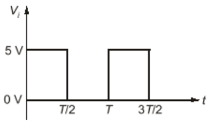


 ∴
∴
 ⇒
⇒ 

 ∴
∴ 

 From (ii),
 ⇒
⇒ 
 Using equation (iii)
 ⇒
⇒ 
⇒ 
 as
as  and
and  ⇒
⇒ 
∴ C = 12.46 μF
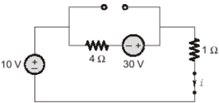
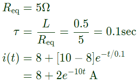
Q5: In the circuit, switch 'S' is in the closed position for a very long time. If the switch is opened at time t = 0, then in iL(t) amperes, for t ≥ 0 is (2021)
 (a) 8e-10t
(b) 10
(c) 8 + 2e-10t
(d) 10(1 - e-2t)
Ans: (c)
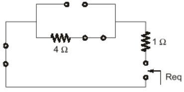
Sol: 
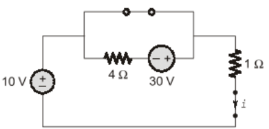

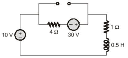 At t = ∞

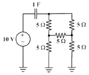
Q6: The initial charge in the 1 F capacitor present in the circuit shown is zero. The energy in joules transferred from the DC source until steady state condition is reached equals ______. (Give the answer up to one decimal place.) (SET-2 (2017))
 (a) 100
(b) 200
(c) 50
(d) 400
Ans: (a)
Sol: Consider the following circuit diagram,
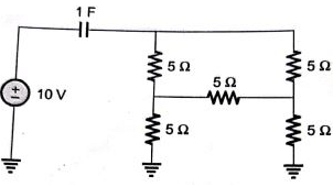 After minimizing circuit elements we can have the following circuit,
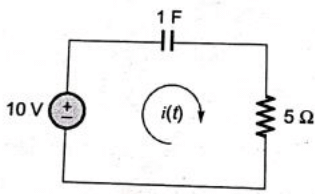
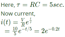 Energy supplied by the source,

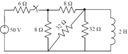
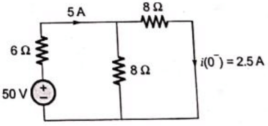
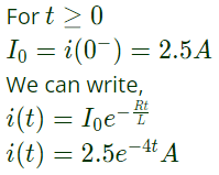
Q7: The switch in the figure below was closed for a long time. It is opened at t = 0. The current in the inductor of 2 H for t ≥ 0, is (SET-1 (2017))
 (a) 2.5 e-4t
(b) 5e-4t
(c) 2.5e-0.25t
(d) 5e-0.25t
Ans: (a)
Sol: From the given circuit, consider the following circuit diagram,
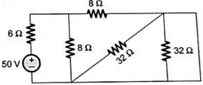 After rearrangement
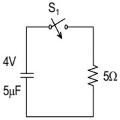
Q8: In the circuit shown below, the initial capacitor voltage is 4 V. Switch S1 is closed at t = 0. The charge (in μC) lost by the capacitor from t = 25 μs to t = 100 μs is ____________. (SET-2(2016))
 (a) 5
(a) 5
(b) 6
(c) 7
(d) 8
Ans: (c)
Sol: 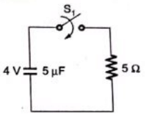
 Change lost by capacitor from t = 25 μs to 100 μs is

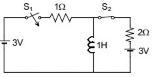
Q9: In the circuit shown, switch S2 has been closed for a long time. At time t = 0 switch S1 is closed. At t = 0+, the rate of change of current through the inductor, in amperes per second, is _____. (SET-1 (2016))
 (a) 1
(a) 1
(b) 2
(c) 3
(d) 4
Ans: (b)
Sol: 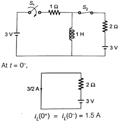
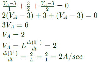
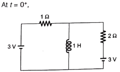 KCL at node A,
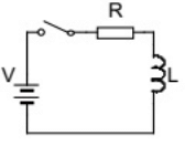
Q10: A series RL circuit is excited at t = 0 by closing a switch as shown in the figure. Assuming zero initial conditions, the value of  is (SET-2 (2015))
 (a) V/L
(b) (-V)/R
(c) 0
(d) (-RV)/(L2)
Ans: (d)
Sol: 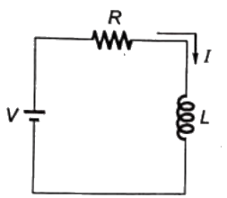 Initially (t = 0−) the inductor would be uncharged.
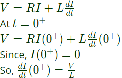
So, I(0+) = 0
The KVL in th loop will be
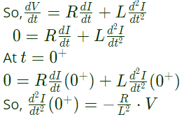
 Now, lets differentiate the above equation
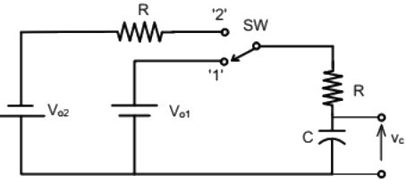
Q11: The switch SW shown in the circuit is kept at position '1' for a long duration. At t = 0+, the switch is moved to position '2'. Assuming ∣Vo2∣ > ∣Vo1∣, the voltage vc(t) across the capacitor is (SET-2 (2014))
 (a)
(a) 
(b) 
(c) 
(d) 
Ans: (d)
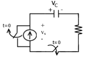
Q12: A combination of 1 μF capacitor with an initial voltage vc(0) = −2V in series with a 100 Ω resistor is connected to a 20 mA ideal dc current source by operating both switches at t = 0s as shown. Which of the following graphs shown in the options approximates the voltage vs across the current source over the next few seconds ? (SET-1 (2014))
 (a)
(a) 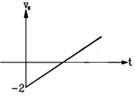 (b)
(b) 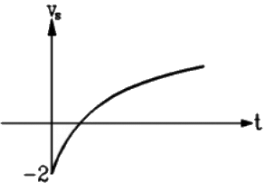 (c)
(c) 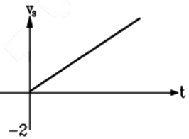 (d)
(d) 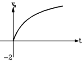 Ans: (c)
Sol: Given C =1μF, Vc(0) = −2V, R= 100Ω, I = 20mA. Circuit fot the given condition at time t > 0 is shown below:
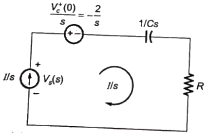 Applying KVL, we have,
 Putting values of R, C and I, we get,
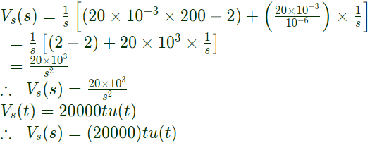 Which is equation of a straight line passing through origin. Hence option (C) is correct.
Q13: In the following figure, C1 and C2 are ideal capacitors. C1 has been charged to 12 V before the ideal switch S is closed at t = 0. The current i(t) for all t is (2012)
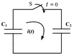 (a) zero
(b) a step function
(c) an exponentially decaying function
(d) an impulse function
Ans: (d)
Sol: 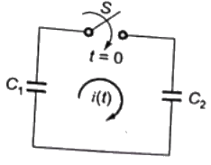 Circuit is s-domain
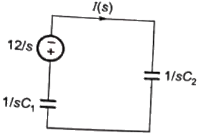 By applying KVL,
 ∴ Current i(t) is an implulse function.
Q14: The L-C circuit shown in the figure has an inductance L = 1mH and a capacitance C = μF.
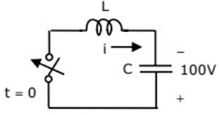 The initial current through the inductor is zero, while the initial capacitor voltage is 100 V. The switch is closed at t = 0. The current i through the circuit (2010)
(a) 5cos(5 × 10³t)A
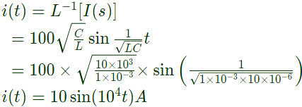
(b) 10sin(104t)A
(c) 10cos(5 × 10³t)A
(d) 10sin(104t)A
Ans: (d)
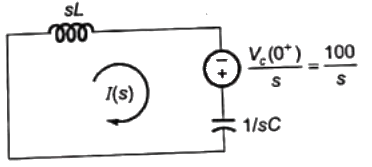
Sol: Initial current through the inductor is zeroand capacitor voltage is charged upto voltage Vc(0−) = 100V
As current through inductor and voltage across capacitor can not change abruptly
So, after closing the switch,
 The circuit id s-domain
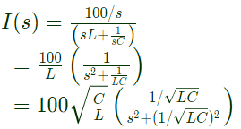 taking inverse laplace transform
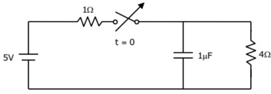
Q15: The switch in the circuit has been closed for a long time. It is opened at t = 0. At t = 0+ , the current through the 1 μF capacitor is (2010)
 (a) 0A
(b) 1A
(c) 1.25 A
(d) 5A
Ans: (b)
Sol: As the switch has been closed for a long time, the circuit is in steady state. At steadystate, capacitor is open circuit,
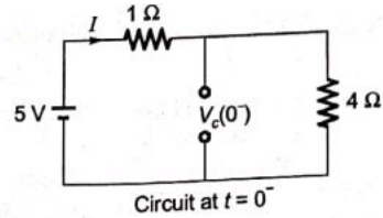 Using KVL,
 As the voltage across capacitorcan not change abruptly,

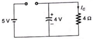 Current through capacitor at t = 0+

 (a) 1.25
 in closed condition. The switch K is closed and
  is opened simultaneously at the instant t = t1, where t1 > 0. The minimum value of t1 in milliseconds, such that there is no transient in the voltage across the 100μF capacitor, is ___ (Round off to 2 decimal places). (2023)
 (a) 0.87
 is closed.
 From circuit, using current division,
 Case (ii) :
 is open.
 From circuit,
 We have,
 For transient free voltage,

 (a) 5
(a) 5 Using voltage division,
 (a) 18.5


 ∴
∴
 ⇒
⇒ 


 ∴
∴ 

 From (ii),
 ⇒
⇒ 
 Using equation (iii)
 ⇒
⇒ 

 as
as  and
and  ⇒
⇒ 
 (a) 8e-10t


 At t = ∞


 (a) 100
 After minimizing circuit elements we can have the following circuit,
 Energy supplied by the source,
 (a) 2.5 e-4t
 After rearrangement

 (a) 5
(a) 5
 Change lost by capacitor from t = 25 μs to 100 μs is
 (a) 1
(a) 1
 KCL at node A,
 is (SET-2 (2015))
 (a) V/L
 Initially (t = 0−) the inductor would be uncharged.
 Now, lets differentiate the above equation
 (a)
(a) 


 (a)
(a)  (b)
(b)  (c)
(c)  (d)
(d)  Ans: (c)
 Applying KVL, we have,
 Putting values of R, C and I, we get,
 Which is equation of a straight line passing through origin. Hence option (C) is correct.
 (a) zero
 Circuit is s-domain
 By applying KVL,
 ∴ Current i(t) is an implulse function.
 The initial current through the inductor is zero, while the initial capacitor voltage is 100 V. The switch is closed at t = 0. The current i through the circuit (2010)
 The circuit id s-domain
 taking inverse laplace transform
 (a) 0A
 Using KVL,
 As the voltage across capacitorcan not change abruptly,
 Current through capacitor at t = 0+


