Q16: In the figure shown, all elements used are ideal. For time t<0, S1 remained closed and S2 open. At t = 0, S1 is opened and S2 is closed. If the voltage VC2 across the capacitor C2 at t = 0 is zero, the voltage across the capacitor combination at t = 0+ will be (2009)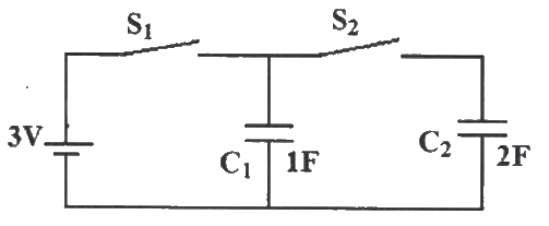
(a) 1 V
(b) 2 V
(c) 1.5 V
(d) 3 V
Ans: (a)
Sol: A t = 0−, S1 is closed, S2 is open
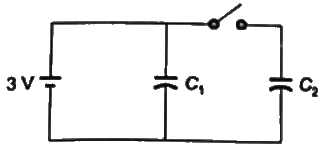 C1 gets charged upto 3 V
Charge stored in C1
 Voltage across C2 is zero at t = 0−, so no charge is stored in C2.
At t > 0, S1 is open and S2 is closed.
Charge stored (Q0) initially in C2 gets redistributed between C1 and C2.
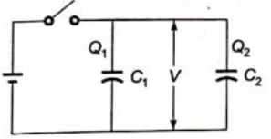 Let charge stored in C1 = Q1
Charge stored in C2 = Q1
According to conservation of charge
Q1 + Q2 = Q0 = 3...(i)
Voltage across C1 =Voltage across C2
 Solving equation (i) and (ii) we get
Q1 = 1C and Q2 = 2C
Voltage across combination = Q1/C1 = 1/1 = 1.
Q17: The current i(t) sketched in the figure flows through a initially uncharged 0.3 nF capacitor.
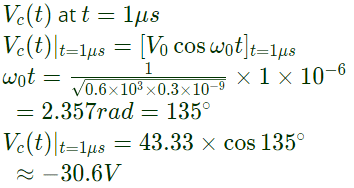
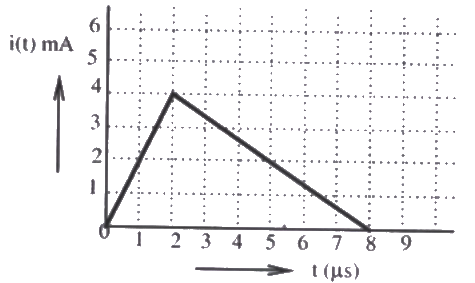 The capacitor charged upto 5 μs, as per the current profile given in the figure, is connected across an inductor of 0.6 mH. Then the value of voltage across the capacitor after 1 μs will approximately be (2008)
(a) 18.8 V
(b) 23.5 V
(c) -23.5 V
(d) -30.6 V
Ans: (d)
Sol: Capacitor charge upto 5μs, so total charge stored in capacitor = Q = 13 nC.
Voltage across the capacitor before connecting to inductor
 Voltage across the capacitor at time t
Q18: The current i(t) sketched in the figure flows through a initially uncharged 0.3 nF capacitor.
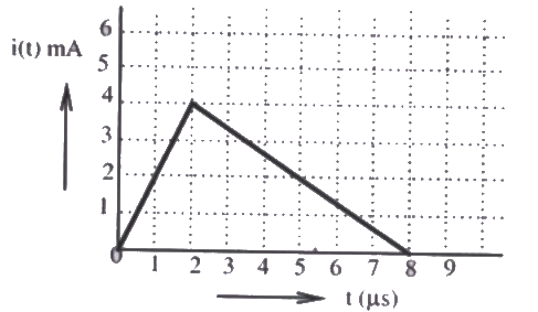 The charge stored in the capacitor at t = 5 μs, will be (2008)
(a) 8 nC
(b) 10 nC
(c) 13 nC
(d) 16 nC
Ans: (c)
Sol: 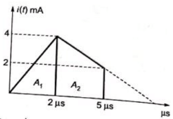 Charged stored in the capcitor =Area under i-t curve

Q19: The time constant for the given circuit will be (2008)
 (a) 1/9 s
(b) 1/4 s
(c) 4s
(d) 9 s
Ans: (c)
Sol: For finding time constant, we neglect current source as a open circuit.
Therefore, circuit becomes

 Therefore, Time constant = ReqCeq
= 6 x (2/3) = 4 sec
Q20: In the circuit shown in figure. Switch SW1 is initially closed and SW2 is open. The inductor L carries a current of 10 A and the capacitor charged to 10 V with polarities as indicated. SW2 is closed at t = 0− and SW1 is opened at t = 0. The current through C and the voltage across L at t = 0+ is (2007)
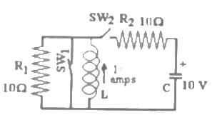 (a) 55 A, 4.5V
(b) 5.5A, 45V
(c) 45A, 5.5V
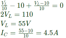
(d) 4.5A, 55V
Ans: (d)
Sol: 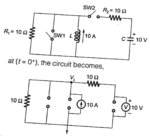 By KCL,
Q21: In the figure, transformer T1 has two secondaries, all three windings having the same number of turns and with polarities as indicated. One secondary is shorted by a 10 Ω resistor R, and the other by a 15 μF capacitor. The switch SW is opened (t = 0) when the capacitor is charged to 5 V with the left plate as positive. At t = 0+ the voltage VP and current IR are (2007)
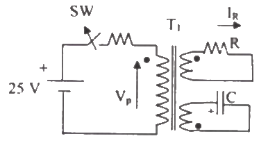 (a) -25 V, 0.0 A
(b) very large voltage, very large current
(c) 5.0 V, 0.5 A
(d) -5.0 V, -0.5 A
Ans: (d)
Sol: 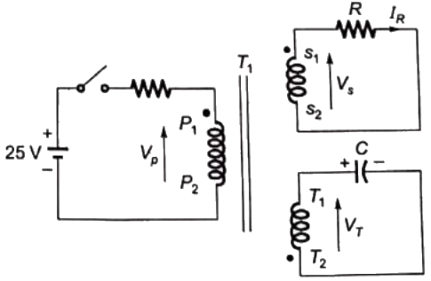 All the three windings has same number of turns, so magnitude of induced emf's in all the three windings will be same i.e.
∣VP∣ = ∣Vs∣ = ∣VT∣
Polarity of the winding is decided on the basis of dot-convention.
As capacitor is carged to 5V with left plate as positive
So, T1 is positive w.r.t. T2
VT = VT1 − VT2 = 5V
As T2 has negative polarity. So P1 has negative polarity.
Therefore , VP = VP1−VP2 = −5V
Similarly, S1 has negative polarity

Q22: An ideal capacitor is charged to a voltage V0 and connected at t = 0 across an ideal inductor L. (The circuit now consists of a capacitor and inductor alone). If we let  the voltage across the capacitor at time t > 0 is given by (2006)
(a) V0
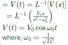
(b) V0 cos (ω0t)
(c) V0 sin (ω0t)
(d) 
Ans: (b)
Sol: Voltage across capacitor will discharge through inductor upto voltage across the capcitor becomes zero. During thos period , electrostatic energy stored in capacitor is transferred into magnetic energy which is stored in inductor.
Now, inductor will start charging capacitor, magnetic energy in inductor is converted into electostatic energy in capacitor.
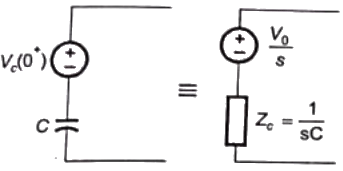
Expression for Vc(t) can be obtained in s-domain. As capacitor is charged initially to voltage V0, then representation of capacitor in s-domain
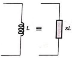
 As current through the inductor is zero at t = 0, then
 The circuit at t > 0


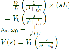 Voltage across the capacitor
Q23: In the circuit shown in the figure, the current source I = 1A, the voltage source V = 5 V, R1 = R2 = R3 = 1Ω, L1 = L2 = L3 = 1H, C1 = C2 = 1F
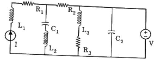 The currents (in A) through R3 and through the voltage source V respectively will be (2006)
(a) 1, 4
(b) 5, 1
(c) 5, 2
(d) 5, 4
Ans: (d)
Sol: In steady state, inductor behaves as short-circuit and capacitor behaves as open-circuit
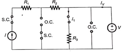 Voltage across, R3 = V = 5V
Current through, 
Apply KCL,
 Current through voltage source
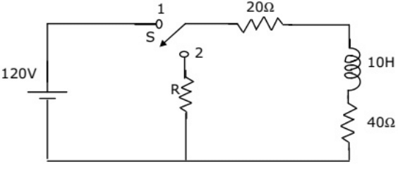
Q24: A coil of inductance 10 H and resistance 40 Ω is connected as shown in the figure. After the switch S has been in contact ith point 1 for a very long time, it is moved to point 2 at, t = 0.
For the value of R = 40Ω, the time taken for 95% of the stored energy to be dissipated is close to (2005)
(a) 0.10 sec
(b) 0.15 sec
(c) 0.50 sec
(d) 1.0 sec
Ans: (b)
Sol: The circuit (in s-domain)
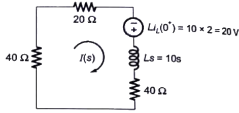
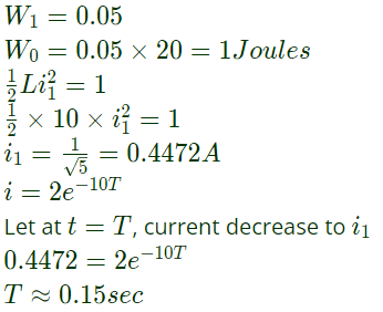
 Initial stored energy in inductor
 Remaining energy in inductor
Q25: A coil of inductance 10 H and resistance 40 Ω is connected as shown in the figure. After the switch S has been in contact ith point 1 for a very long time, it is moved to point 2 at, t = 0.
If, at t = 0+, the voltage across the coil is 120 V, the value of resistance R is (2005)
 (a) 0 Ω
(b) 20 Ω
(c) 40 Ω
(d) 60 Ω
Ans: (c)
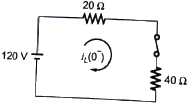
Sol: Before moving the switch at t = 0−
The circuit is in steady state and inductor behaves as short-circuit.
The circuit at t = 0−

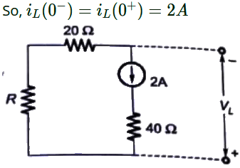
 After moving the switch at 𝑡 = 0+
Current through inductor can not change abruptly.

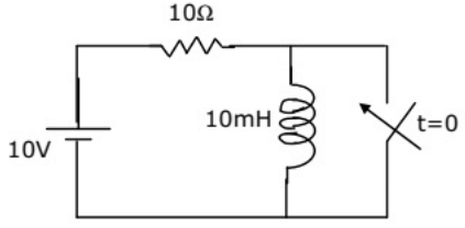
Q26: The circuit shown in the figure is in steady state, when the switch is closed at t = 0. Assuming that the inductance is ideal, the current through the inductor at t = 0+ equals (2005)
 (a) 0 A
(b) 0.5 A
(c) 1 A
(d) 2 A
Ans: (c)
Sol: Before closing the switch, at t = 0−, the circuit is in steady state. So, inductor behaves as short-circuit
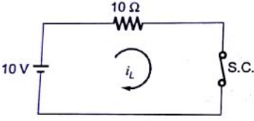
 After closing the switch, at t = 0+
Current through inductor can not change abruptly.

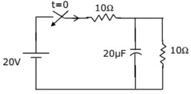
Q27: In the figure given, the initial capacitor voltage is zero. The switch is closed at t = 0. The final steady-state voltage across the capacitor is (2005)
 (a) 20 V
(b) 10 V
(c) 5 V
(d) 0 V
Ans: (b)
Sol: At (t → 0+). The capacitor act as short-circuit. At (t → ∞), the capacitor will become open circuit.
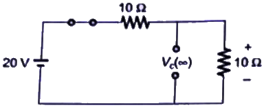 Therefore, voltage across capacitor =
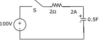
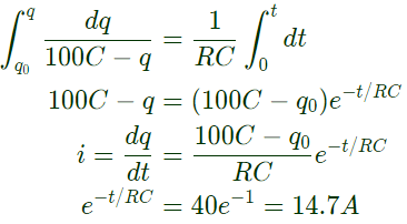
Q28: In figure, the capacitor initially has a charge of 10 Coulomb. The current in the circuit one second after the switch S is closed will be (2004)
 (a) 14.7 A
(b) 18.5 A
(c) 40.0 A
(d) 50.0 A
Ans: (a)
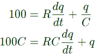
Sol: Using KVL,
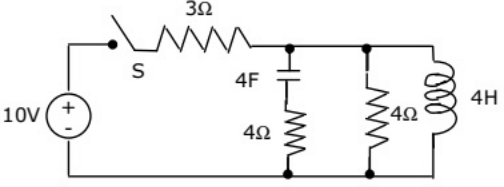
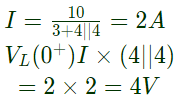
Q29: In the circuit shown in figure, the switch S is closed at time (t = 0). The voltage across the inductance at t = 0+, is (2003)
 (a) 2 V
(b) 4 V
(c) -6 V
(d) 8 V
Ans: (b)
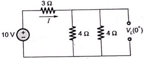
Sol: Before closing the switch, the circuit was not energized, therefore, current through inductor and voltage across capacitor are zero.
After closing the switch, at t = 0+ inductor acts as open-circuit and capacitor acts as shortc ircuit. Equivalent circuit at t = 0+
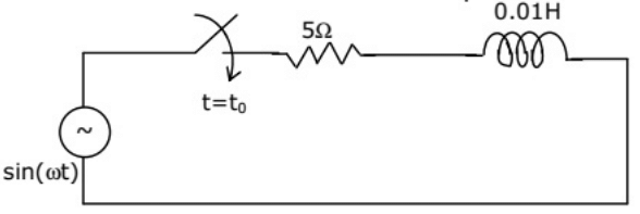
Q30: Consider the circuit shown in figure. If the frequency of the source is 50 Hz, then a value of t0 which results in a transient free response is (2002)
 (a) 0 ms
(b) 1.78 ms
(c) 2.71 ms
(d) 2.91 ms
Ans: (b)
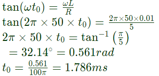
Sol: For transient free response,
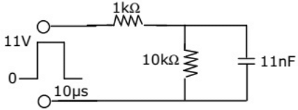
Q31: An 11 V pulse of 10 μs duration is applied to the circuit shown in figure. Assuming that the capacitor is completely discharged prior to applying the pulse, the peak value of the capacitor voltage is (2002)
 (a) 11 V
(b) 5.5 V
(c) 6.32 V
(d) 0.96 V
Ans: (c)
Sol:  and
and
∵ pulse of duration 10μs is applies. Hence, capacitor charges till 10μs and then starts discharging, so Vc will be maximum at t = 10μs.
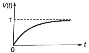
Q32: A unit step voltage is applied at t = 0 to a series RL circuit with zero initial conditions. (2001)
(a) It is possible for the current to be oscillatory.
(b) The voltage across the resistor at t = 0+ is zero.
(c) The energy stored in the inductor in the steady state is zero.
(d) The resistor current eventually falls to zero.
Ans: (b)
Sol: At t = 0+ inductor works as open circuit. Hence, complete source voltage drops across it and consequently, current through the resistor R is zero. Hence, voltage across the resistor at t = 0+ is zero. And further with time it rises accroding to VR(t) = (1−e−Rt/L)u(t).

 C1 gets charged upto 3 V
 Voltage across C2 is zero at t = 0−, so no charge is stored in C2.
 Let charge stored in C1 = Q1
 Solving equation (i) and (ii) we get
 The capacitor charged upto 5 μs, as per the current profile given in the figure, is connected across an inductor of 0.6 mH. Then the value of voltage across the capacitor after 1 μs will approximately be (2008)
 Voltage across the capacitor at time t
 The charge stored in the capacitor at t = 5 μs, will be (2008)
 Charged stored in the capcitor =Area under i-t curve
 (a) 1/9 s
 Therefore, Time constant = ReqCeq
 (a) 55 A, 4.5V
 By KCL,
 (a) -25 V, 0.0 A
 All the three windings has same number of turns, so magnitude of induced emf's in all the three windings will be same i.e.
 the voltage across the capacitor at time t > 0 is given by (2006)
 As current through the inductor is zero at t = 0, then
 The circuit at t > 0

 Voltage across the capacitor
 The currents (in A) through R3 and through the voltage source V respectively will be (2006)
 Voltage across, R3 = V = 5V
 Current through voltage source

 Initial stored energy in inductor
 Remaining energy in inductor
 (a) 0 Ω
 After moving the switch at 𝑡 = 0+

 (a) 0 A
 After closing the switch, at t = 0+
 (a) 20 V
 Therefore, voltage across capacitor =
 (a) 14.7 A

 (a) 2 V

 (a) 0 ms
 (a) 11 V
 and
and


