RL Circuit : Working and Applications | Physics for JEE Main & Advanced PDF Download
| Table of contents |
|
| What are RL Circuits? |
|
| Types of RL Circuits: Series and Parallel |
|
| Growth and Decay of Current in L-R Circuit |
|
| Applications of LR Circuits |
|

Have you ever wondered how radio wave transmitters or other communication systems work? These all systems contain special circuits called LR circuits. In this document, we will study these circuits in detail.
What are RL Circuits?
The resistor and inductor are the most fundamental linear (element having linear relationship between voltage and current) and passive (which consume energy) elements. When resistor and inductor are connected across voltage supply, the circuit so obtained is called RL circuit.
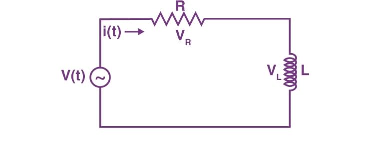 RL Circuit
VR is the voltage across resistor R
VL is the voltage across inductor L
V(t) is the total voltage across the circuit.
Types of RL Circuits: Series and Parallel
RL circuit can be connected in two ways: Series and Parallel as shown in the figure below:
 Types of RL Circuit
- RL Series Circuit- When resistance and inductor are connected in series with voltage supply. The circuit is called series RL circuit.
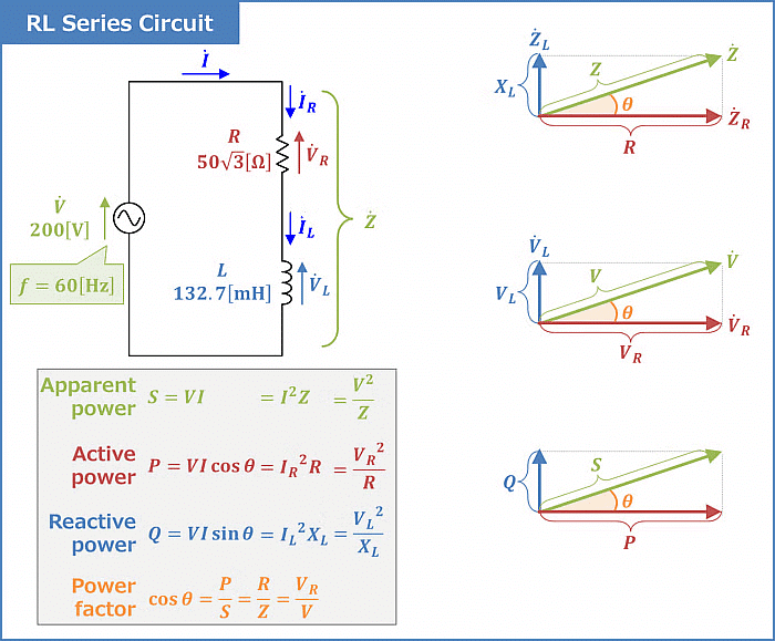 Important formulas for Series RL Circuit
 - RL Parallel Circuit- When resistance and inductor are connected in parallel with each other and is driven by voltage source, the circuit so obtained is called parallel RL circuit.
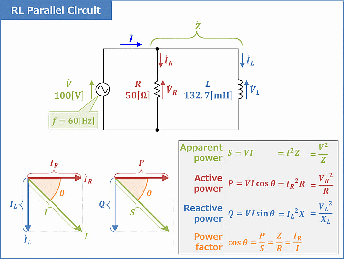 Important Formulas for Parallel RL Circuit
Example 1. Find the value of current i, i1, and i2 in the given figure at
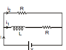
(a) time t = 0
(b) time t = ∞
Answer: (a) At time t = 0 inductor behaves as an open circuit
i = v/R
i1 = 0
i2= i = v/R 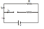
(b) At time t = ∞. The inductor will behave as a simple wire
i = 
i1 = i2 = 
Growth and Decay of Current in L-R Circuit
Growth of Current
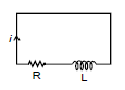
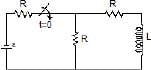
- Consider a circuit containing a resistance R, an inductance L, a two-way key, and a battery of e.m.f E connected in series as shown in the figure.
- When the switch S is connected to a, the current in the circuit grows from zero value. The inductor opposes the growth of the current.
- This is due to the fact that when the current grows through an inductor, a back e.m.f. is developed which opposes the growth of current in the circuit.
- So the rate of growth of the current is reduced. During the growth of current in the circuit, let i be the current in the circuit at any instant t. Using Kirchhoff's voltage law in the circuit, we obtain

E - L  = R i or E - Ri = L
  or
or 
Multiplying by - R on both sides, we get

Integrating the above equation, we have
loge(E - Ri) = -  + A ...(1)
where A is the integration constant. The value of this constant can be obtained by applying the condition that current i is zero just at the start i.e., at t = 0.
Hence,
loge E = 0 + A
or A = logeE ...(2)
Substituting the value of A from equation (2) in equation (1), we get
loge(E - Ri) = -  + loge E
or loge =
= 
or  = exp
= exp 
or 1 -  = exp
= exp
or 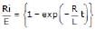
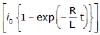
Therefore, i = 
The maximum current in the circuit i0 = E/R.
So, i = i0  ...(3)
Equation (3) gives the current in the circuit at any instant t. It is obvious from equation (3) that i = i0, when
exp = 0 i.e., at t = ∞
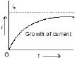
Hence the current never attains the value i0 but it approaches it asymptotically. A graph between current and time is shown in the figure.
We observe the following points
(i) When t = (L/R) then
i = i0  = i0 {1 - exp(-1)} = i0
  = 0.63 i0
Thus after an interval of (L/R) second, the current reaches a value that is 63% of the maximum current. The value of (L/R) is known as the time constant of the circuit and is represented by t. Thus the time constant of a circuit may be defined as the time in which the current rises from zero to 63% of its final value. In terms of t,

(ii) The rate of growth of current (di/dt) is given by
 =
= 
 ⇒
⇒ 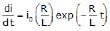 ...(4)
From equation (3), exp  =
= 
Therefore,  =
=  ...(5)
This shows that the rate of growth of the current decreases as i tends to i0. For any other value of current, it depends upon the value of R/L. Thus greater the value of the time constant, the smaller will be the rate of growth of the current.
Note:
Final current in the circuit =
, which is independent of L.
After one time constant, current in the circuit=63% of the final current (verify yourself)
More time constant in the circuit implies slower rate of change of current.
If there is any change in the circuit containing inductor then there is no instantaneous effect on the flux of inductor.
L1i1 = L2i2
Example 2. At t = 0 switch is closed (shown in figure) after a long time suddenly the inductance of the inductor is made h times lesser  than its initial value, find out the instant current just after the operation.

Ans. Using the above result (note 4)
L1i1 = L2i2 ⇒ i2 = 
Example 3. Which of the two curves shown has less time constant?

Ans. curve 1
Decay of Current
Let the circuit be disconnected from the battery and switch S is thrown to point b in the figure. The current now begins to fall. In the absence of inductance, the current would have fallen from maximum i0 to zero almost instantaneously. However, due to the presence of inductance, which opposes the decay of current, the rate of decay of current is reduced.
suppose during the decay of current, i is the value of current at any instant t. Using Kirchhoff's voltage law in the circuit, we get
- L or
or 
Integrating this expression, we get
loge i = -  + B
+ B
where B is the constant of integration. The value of B can be obtained by applying the condition that when t = 0, i = i0
Therefore, loge i0 = B
Substituting the value of B, we get
logei = -  + logei0
or loge = -
= - 
or (i/i0) = exp ...(6)
or 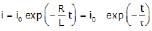
where t = L/R = inductive time constant of the circuit.
It is obvious from the equation that the current in the circuit decays exponentially as shown in figure.
We observe the following points
(i) After t = L/R, the current in the circuit is given by
i = i0 exp = i0 exp(-1)
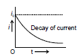
= (i0 / e) = i0/2.718 = 0.37 i0
So after a time (L/R) second, the current reduces to 37% of the maximum current i0. (L/R) is known as time constant t. This is defined as the time during which the current decays to 37% of the maximum current during decay.
(ii) The rate of decay of current is given by
 =
= 
⇒  =
=  i0 exp
  =
=  ...(7)
or -  =
= 
This equation shows that when L is small, the rate of decay of current will be large i.e., the current will decay out more rapidly.
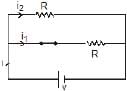
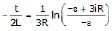
Example 4. In the following circuit, the switch is closed at t = 0. Initially, there is no current in the inductor. Find out the current of the inductor coil as a function of time.
Ans: At any time t
- e + i1 R - (i - i1) R = 0
- e + 2i1 R - i R = 0
i1 = 
Now, - e + i1 R + iR +L. = 0
= 0 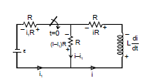
- e +  + iR + i.
  ⇒ -
⇒ - 
 dt = - L. di ⇒
-  ⇒
⇒ 
- ln  =
= 
i = + 
Example 5. Figure shows a circuit consisting of an ideal cell, an inductor L, and a resistor R, connected in series. Let the switch S be closed at t = 0. Suppose at t = 0 current in the inductor is i0 then find out the equation of current as a function of time

Ans: Let an instant t current in the circuit is i which is increasing at the rate di/dt.
Writing KVL along the circuit, we have
ε - L - iR = 0 ⇒
  = ε - iR
⇒  ⇒ ln
⇒ ln  = -
= - 
⇒ ε - iR = (ε - i0R)e-Rt/L ⇒ i = 
Applications of LR Circuits
- RL circuits are frequently employed in systems utilizing Alternating Current (AC). Within AC circuits, the current continually fluctuates, resulting in a consistent induction of an Electromotive Force (EMF) across the inductor.
- One way in which RL circuits are utilized in AC systems is as a frequency filter, achieved by configuring the circuit in such a way that signals or alternating currents of a specific frequency are obstructed by the robust opposing EMF. This function plays a crucial role in radio communication, where the ability to select signals frequently.
|
268 videos|732 docs|171 tests
|
FAQs on RL Circuit : Working and Applications - Physics for JEE Main & Advanced
| 1. What is the difference between a series RL circuit and a parallel RL circuit? |  |
| 2. How does the current in an L-R circuit change over time? | |
| 3. What are some applications of RL circuits? | |
| 4. How does an RL circuit work? | |
| 5. What are some frequently asked questions about RL circuits in JEE exams? | |


video lectures
,Semester Notes
,Summary
,Extra Questions
,ppt
,Important questions
,MCQs
,RL Circuit : Working and Applications | Physics for JEE Main & Advanced
,mock tests for examination
,Sample Paper
,Viva Questions
,shortcuts and tricks
,past year papers
,practice quizzes
,Free
,Previous Year Questions with Solutions
,Objective type Questions
,RL Circuit : Working and Applications | Physics for JEE Main & Advanced
,Exam
,study material
,RL Circuit : Working and Applications | Physics for JEE Main & Advanced
;


RL Circuit : Working and Applications Free PDF Download
Importance of RL Circuit : Working and Applications
RL Circuit : Working and Applications Notes
RL Circuit : Working and Applications JEE Questions
Study RL Circuit : Working and Applications on the App
|
© EduRev
|
Education Revolution
|


|


