Resultant Forces & Free Body Diagrams | Physics for Grade 10 PDF Download
| Table of contents |

|
| Resultant Force |

|
| Examples of Forces |

|
| Free Body Diagrams |

|
| Resolving Forces |

|
| Using Scale Drawings |

|
Resultant Force
- A resultant force is a single force that describes all of the forces operating on a body
- When many forces are applied to an object they can be combined (added) to produce one final force which describes the combined action of all of the forces
- This single resultant force determines:
- The direction in which the object will move as a result of all of the forces
- The magnitude of the final force experienced by the object
- The resultant force is sometimes called the net force
- Forces can combine to produce
- Balanced forces
- Unbalanced forces
- Balanced forces mean that the forces have combined in such a way that they cancel each other out and no resultant force acts on the body
- For example, the weight of a book on a desk is balanced by the normal force of the desk
- As a result, no resultant force is experienced by the book, the book and the table are equal and balanced
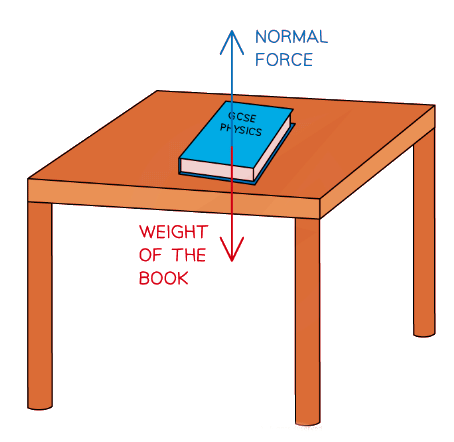 A book resting on a table is an example of balanced forces
- Unbalanced forces mean that the forces have combined in such a way that they do not cancel out completely and there is a resultant force on the object
- For example, imagine two people playing a game of tug-of-war, working against each other on opposite sides of the rope
- If person A pulls with 80 N to the left and person B pulls with 100 N to the right, these forces do not cancel each other out completely
- Since person B pulled with more force than person A the forces will be unbalanced and the rope will experience a resultant force of 20 N to the right
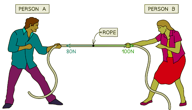 A tug-of-war is an example of when forces can become unbalanced
- Resultant forces can be calculated by adding or subtracting all of the forces acting on the object
- Forces working in opposite directions are subtracted from each other
- Forces working in the same direction are added together
- If the forces acting in opposite directions are equal in size, then there will be no resultant force – the forces are said to be balanced
 Diagram showing the resultant forces on three different objects
 - Imagine the forces on the boxes as two people pushing on either side
- In the first scenario, the two people are evenly matched - the box doesn't move
- In the second scenario, the two people are pushing on the same side of the box, it moves to the right with their combined strength
- In the third scenario, the two people are pushing against each other and are not evenly matched, so there is a resultant force to the left
Example: Calculate the magnitude and direction of the resultant force in the diagram below.
Step 1: Add up all of the forces directed to the right
4 N + 8 N = 12 NStep 2: Subtract the forces on the right from the forces on the left
14 N – 12 N = 2 NStep 3: Evaluate the direction of the resultant force
The force to the left is greater than the force to the right therefore the resultant force is directed to the leftStep 4: State the magnitude and direction of the resultant force
The resultant force is 2 N to the left
Tip
Remember to always provide units for your answer and to state whether the force is to the left, to the right, or maybe up or down
Always provide your final answer as a description of the magnitude and the direction, for example:
- Resultant Force = 4 N to the right
Examples of Forces
Tension
- Tension is:
- The force experienced by a cable, rope, or string when pulled, hung, rotated or supported
- This is normally labelled as T on free body diagrams
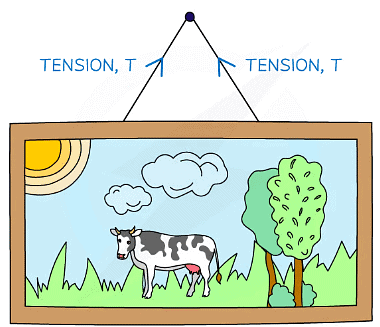 Tension always acts away from the mass
Normal Contact Force
- The normal contact force is:
- The force arising when an object rests against another object acting at a 90° angle to the plane of contact
- It is sometimes also referred to as the reaction force
- This is normally labelled as N or R on free body diagrams
- This force arises from Newton's Third Law
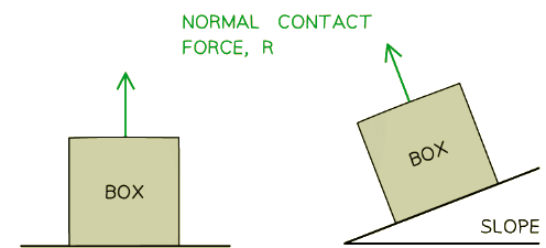 Normal contact force always acts perpendicular to the surface
Upthrust
- Upthrust is:
- The upward buoyancy force acting on an object when it is in a fluid
- Upthrust can occur in liquids and gases
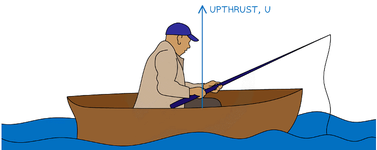 Upthrust always acts upwards
Friction
- Friction is:
- The force that arises when two surfaces are in contact with each other
- Friction always opposes the motion
- This is normally labelled as F or Fr on free body diagrams
 Friction always acts at the point where the objects are in contact, and in the opposite direction to the direction of motion
Free Body Diagrams
- Free body diagrams are useful for modelling the forces that are acting on an object
- Each force is represented as a vector arrow, where each arrow:
- Is scaled to the magnitude of the force it represents
- Points in the direction that the force acts
- Is labelled with the name of the force it represents
- Free body diagrams can be used:
- To identify which forces act in which plane
- To resolve the net force in a particular direction
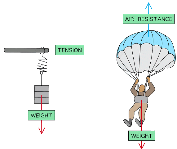 Free body diagrams can be used to show the various forces acting on objects
Example: Draw free-body diagrams for the following scenarios:
(a) A picture frame hanging from a nail
(b) A box sliding down a slope
(c) A man fishing in a stationary boat
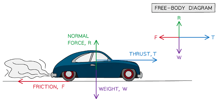
(d) A car accelerating along a road
Part (a)
The size of the arrows should be such that the 3 forces would make a closed triangle as they are balanced
Part (b)
(i) There are three forces acting on the box
(ii) The normal contact force, R, acts perpendicular to the slope
(iii) Friction, F, acts parallel to the slope and in the opposite direction to the direction of motion
(iv) Weight, W, acts down towards the EarthPart (c)
As the boat is not moving, the size of both arrows must be the Part (d)
Part (d)
(i) As the car is accelerating, the size of the thrust must be larger than the size of the friction force
(ii) As in part (c), the upwards and downwards forces must be equal
Example: Draw a free-body diagram of an toy sail boat with weight 30N floating in water that is being pulled to the right by an applied force of 35N.
Step 1: Draw the object in a simplified diagramStep 2: Identify all of the forces acting upon the object in the question, including any forces that may be implied
(i) Weight: 30N down
(ii) Upthrust from the water (since the object is floating): 30N up
(iii) Applied force: 35N to the rightStep 2: Draw in all of the force vectors (arrows), making sure the arrows start at the object and are directed away
An approximation can be made as to the final resultant force due to all of the forces
(i) Decide whether the resultant force is approximately up or down
(ii) Decide whether the resultant force is approximately left or right
(iii) For example: The resultant force is directed up and to the right
Resolving Forces
- Combining more than one force vector can result in
- Balanced forces - where there is no resultant force
- Unbalanced forces - where there is a resultant force
- If a force acts at an angle, the force may be broken down or resolved
- A single force can be resolved into two parts (components)
- A horizontal component
- A vertical component
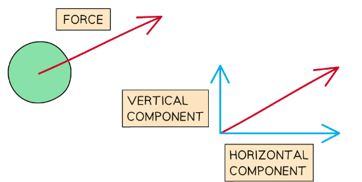 The force (shown in red) may be broken into two components (shown in blue): a vertical one and a horizontal one
- When several forces act on an object in different directions, the resultant force can be found by adding the arrows together
- The two component arrows are placed head to tail with the single force starting at the tail of the first vector and ending at the head of the second
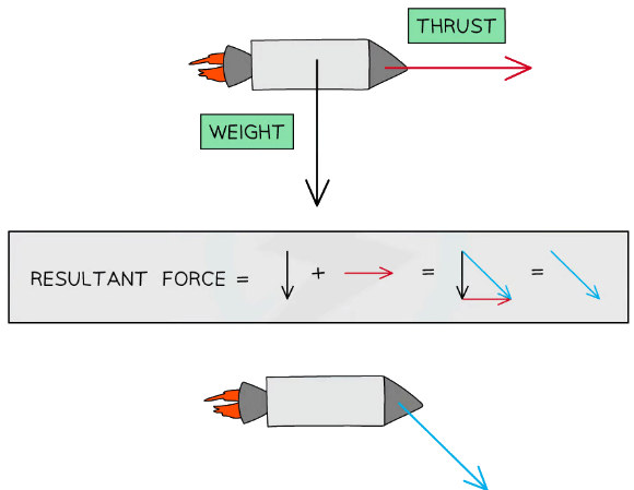 The resultant force can be found by adding the arrows together in a “head to tail” manner
 - If the force arrows from a closed loop, then the forces are balanced, in other words, there is no resultant force
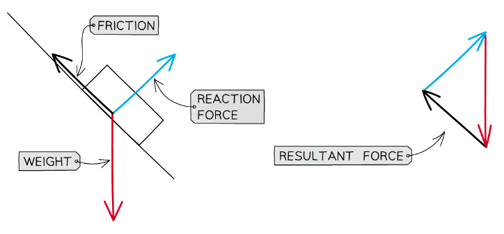 The forces in the above diagram form a closed loop – they are balanced
Tip: The resultant force is sometimes also known as the net force or the unbalanced force, so if you see any of these phrases used in an exam - don't panic, they all mean the same thing!
Using Scale Drawings
- Resolving vectors into components allows for more accurate calculations of resultant forces
- By resolving all of the involved forces into their horizontal and vertical components and then adding or subtracting as required, a final resultant force vector can be constructed using a scale diagram
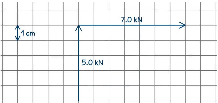
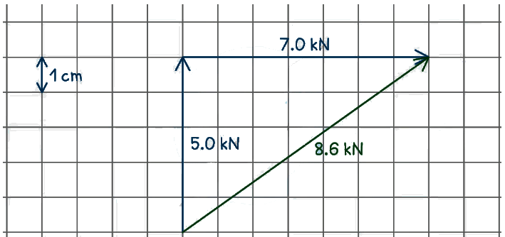
Example: The diagram below shows two rhinos pushing against a vehicle. The two forces are at right angles to each other.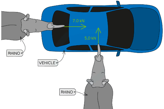 Draw a scale vector diagram to determine the magnitude of the resultant force. Label the two forces applied and the resultant, and clearly state the scale used.
Step 1: Decide on a suitable scale
- A scale of 1 cm to 1.0 kN is the most suitable for this scenario
Step 2: Use grid paper to draw the vectors top to tail and to scale
Step 3: Draw the resultant vector and measure its length
Step 4: Use the scale to convert the length to kN
The resultant force is 8.6 cm, meaning the resultant force is equal to 8.6 kN
|
122 videos|150 docs|40 tests
|

