Series Resonance | Network Theory (Electric Circuits) - Electrical Engineering (EE) PDF Download
| Table of contents |
|
| Introduction |
|
| What is Series Resonance? |
|
| Phasor Diagram: |
|
| Frequency Response |
|
| Series Resonance Circuit Diagram |
|
| Parameters & Electrical Quantities at Resonance |
|
Introduction
Resonance occurs in electric circuits due to the presence of energy storing elements like inductor and capacitor. It is the fundamental concept based on which, the radio and TV receivers are designed in such a way that they should be able to select only the desired station frequency.
There are two types of resonances, namely series resonance and parallel resonance. These are classified based on the network elements that are connected in series or parallel.
In this document, let us discuss about series resonance.
What is Series Resonance?
Resonance in electric circuits is because of the presence of energy storing elements called capacitor and inductor. At a fixed frequency f0, the elements L and C will exchange their energy freely as a function of time which results in sinusoidal oscillations either across inductor (or) capacitor.
Consider a series RLC circuit at resonance.
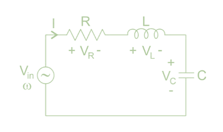
Z = R + jωL +1/jωC
= R + j (ωL − 1/ωC)
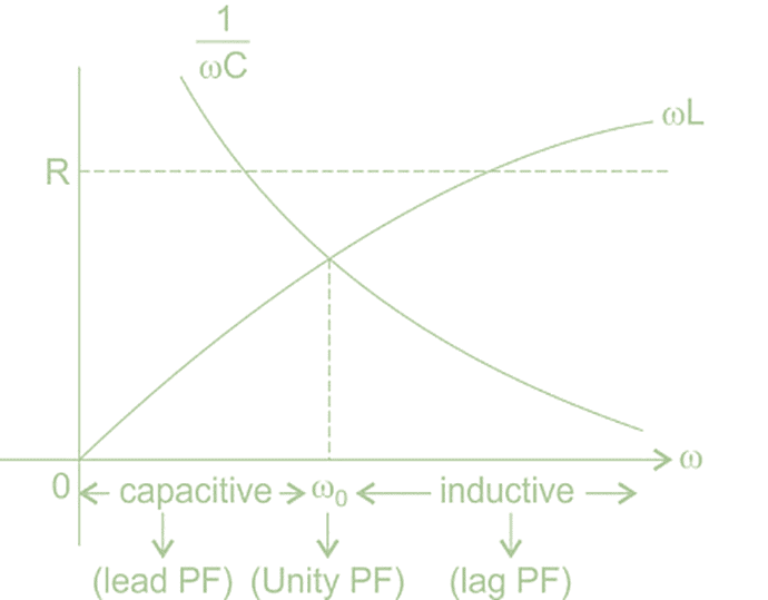
At resonance impedance is purely real i. e. ω0L =1/ω0C
∴ ω0 = 1/√LC
Z(jω0 ) = R
At ω = ω0,
VR = IR = V
VL = Q. V∠90° where Q = ωL/R
VC = Q. V∠ − 90° where Q = 1/ωCR
The behavior of series RLC circuit is given by
Phasor Diagram:
Notes:
i. The LC combination in a series RLC circuit acts like a short circuit at resonance.
ii. At resonance the AC circuit behaves like dc circuit.
iii. Generally, the series RLC circuit frequency response is similar to band pass filter
response.
Frequency Response
Bandwidth = fH − fL =f0/Q
Where, Q = ω0L/R = 1/ω0CR
Also √fH. fL = f0
Note:
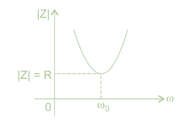
i. At resonance, Z is minimum ⇒ I = maximum ⇒ so it is called acceptor circuit.
ii. Since voltage across L and C elements are magnified by ‘Q’ times, hence series RLC
circuit at resonance is also called as voltage magnification circuit.
Q =ω0L/R = 1/ω0CR = (1/R)x (√(L/C) = ω0 × (Maximum energy stored in L and C at resonance / Average power dissipated at resonance)
iv. As Q is more ⇒ circuit is said to be more selective and oscillations produced are of high
quality.
v. For the physical existence of the circuit a minimum R is to be maintained in the circuit
which is known as critical resistance of the circuit, where damping ratio is 1.
For finding resonant frequency always equal the imaginary part of impedance (or) admittance to be zero.

Series Resonance Circuit Diagram
If the resonance occurs in series RLC circuit, then it is called as Series Resonance. Consider the following series RLC circuit, which is represented in phasor domain.
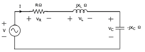
Here, the passive elements such as resistor, inductor and capacitor are connected in series. This entire combination is in series with the input sinusoidal voltage source.
Apply KVL around the loop:
V−VR−VL−VC = 0
⇒ V−IR−I(jXL)−I(−jXC) = 0
⇒ V = IR+I(jXL)+I(−jXC)
⇒ V = I[R+j(XL−XC)] Equation 1
The above equation is in the form of V = IZ.
Therefore, the impedance Z of series RLC circuit will be:
Z = R + j(XL−XC)
Parameters & Electrical Quantities at Resonance
Now, let us derive the values of parameters and electrical quantities at resonance of series RLC circuit one by one.
(a) Resonant Frequency
The frequency at which resonance occurs is called as resonant frequency fr. In series RLC circuit resonance occurs, when the imaginary term of impedance Z is zero, i.e., the value of XL − XC should be equal to zero.
⇒ XL = XC
Substitute XL = 2πfL and  in the above equation.
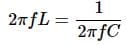
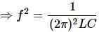
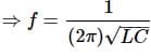
Therefore, the resonant frequency fr of series RLC circuit is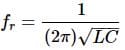
Where, L is the inductance of an inductor and C is the capacitance of a capacitor.
The resonant frequency fr of series RLC circuit depends only on the inductance L and capacitance C. But, it is independent of resistance R.
(b) Impedance
We got the impedance Z of series RLC circuit as
Z = R+j(XL − XC)
Substitute XL = XC in the above equation.
Z = R+j(XC − XC)
⇒ Z = R+j(0)
⇒ Z = R
At resonance, the impedance Z of series RLC circuit is equal to the value of resistance R, i.e., Z = R.
(c) Current flowing through the Circuit
Substitute XL − XC = 0 in Equation 1
V = I[R+j(0)]
⇒ V = IR
⇒ I = V/R
Therefore, current flowing through series RLC circuit at resonance is I = V/R
At resonance, the impedance of series RLC circuit reaches to minimum value. Hence, the maximum current flows through this circuit at resonance.
(d) Voltage across Resistor
The voltage across resistor is
VR = IR
Substitute the value of I in the above equation.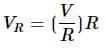
⇒ VR = V
Therefore, the voltage across resistor at resonance is VR = V.
(e) Voltage across Inductor
The voltage across inductor is
VL = I(jXL)
Substitute the value of I in the above equation.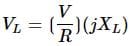
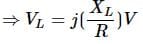
⇒ VL = jQV
Therefore, the voltage across inductor at resonance is VL = jQV.
So, the magnitude of voltage across inductor at resonance will be
|VL| = QV
Where Q is the Quality factor and its value is equal to 
(f) Voltage across Capacitor
The voltage across capacitor is
VC = I(−jXC)
Substitute the value of I in the above equation.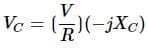
⇒ VC = −jQV
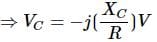
Therefore, the voltage across capacitor at resonance is VC = −jQV.
So, the magnitude of voltage across capacitor at resonance will be
|VC| = QV
Where Q is the Quality factor and its value is equal to
Note: Series resonance RLC circuit is called as voltage magnification circuit, because the magnitude of voltage across the inductor and the capacitor is equal to Q times the input sinusoidal voltage V.
 RLC Resonance
Example 1: In a series RLC circuit, R = 10 Ω, XL = 20 and XC = 20. Then determine the voltage across the inductor if VS = 100 V.
Solution:
Given, XL = XC = 20
∴ Circuit is in resonance
∴VS = VR = 100V
Q − factor = ωL/R = XL/R = 20/10 = 2
∴ Voltage across inductor VL = V.Q∠90°
=100.2∠90° = 200j
∴ Magnitude of VL = 200V
Example 2: Determine the resonant frequency of the circuit given below:
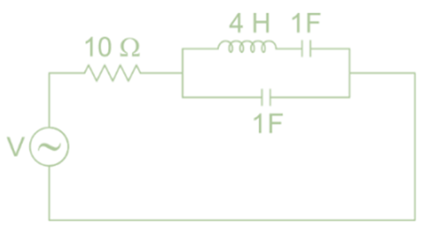
Solution: The impedance of above circuit is given by:
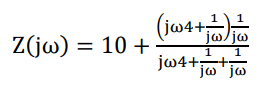
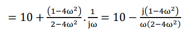
For resonance, imaginary part = 0
∴ 1 – 4ω2 = 0, ∴ ω0 = ½ = 0.5
|
68 videos|85 docs|62 tests
|
FAQs on Series Resonance - Network Theory (Electric Circuits) - Electrical Engineering (EE)
| 1. What is Series Resonance? |  |
| 2. How is Series Resonance depicted in a Phasor Diagram? | |
| 3. What is the Frequency Response of a Series Resonance circuit? | |
| 4. Can you provide a Circuit Diagram of a Series Resonance Circuit? | |
| 5. What are the Parameters and Electrical Quantities at Resonance in a Series Resonance Circuit? | |

|
4.95/5 Rating |

|
Jan 01, 2025 Last updated |

|
Explore Courses for Electrical Engineering (EE) exam
|
|
study material
,Series Resonance | Network Theory (Electric Circuits) - Electrical Engineering (EE)
,video lectures
,Objective type Questions
,Viva Questions
,mock tests for examination
,ppt
,Free
,Exam
,Extra Questions
,Previous Year Questions with Solutions
,Semester Notes
,Series Resonance | Network Theory (Electric Circuits) - Electrical Engineering (EE)
,shortcuts and tricks
,past year papers
,Summary
,practice quizzes
,Sample Paper
,MCQs
,Series Resonance | Network Theory (Electric Circuits) - Electrical Engineering (EE)
,Important questions
;


Series Resonance Free PDF Download
Importance of Series Resonance
Series Resonance Notes
Series Resonance Electrical Engineering (EE) Questions
Study Series Resonance on the App
|
© EduRev
|
Education Revolution
|


|


