Shear Center - Civil Engineering (CE) PDF Download

Shear center
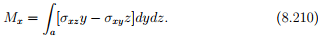
Having found the solution to symmetrical and asymmetrical bending, in this section we find where the load has to be applied so that it produces no torsion. Shear center is defined as the point about which the external load has to be applied so that it produces no twisting moment. Recall from equation (8.7) the torsional moment due to the shear force σxy and σxz about the origin is,
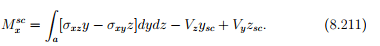
Since, 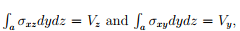 the moment about some other point (ysc, zsc) would be,
If this point (ysc, zsc) is the shear center, then  = 0. Thus, we have to find ysc and zsc such that,
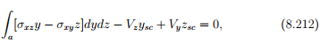
holds. We have two unknowns but only one equation. Hence, we cannot find ysc and zsc uniquely, in general. If the loading is such that only shear force Vy is present, then
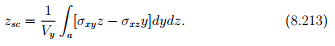
Similarly, if Vy = 0,
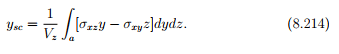
Equations (8.213) and (8.214) are used to find the coordinates of the shear center with respect to the chosen origin of the coordinate system, which for homogeneous sections is usually taken as the centroid of the cross section. Thus, the point that (ysc, zsc) are the coordinates of the shear center from the origin of the chosen coordinate system which in many cases would be the centroid of the section cannot be overemphasized. In the case of thin walled sections which develop shear stresses tangential to the cross section, σxy = −τ sin(θ) and σxz = τ cos(θ), where τ is the magnitude of the shear stress and θ is the angle the tangent to the cross section makes with the z direction. By virtue of the shear stress depending linearly on the shear force (see equations (8.43) and (8.207)), it can be seen that the coordinates of the shear center is a geometric property of the section.
Illustrative examples
Next, to illustrate the use of equations (8.213) and (8.214) we find the shear center for some shapes.
Example 1: Rectangular section
The first section that we consider is a thick walled rectangular section as shown in figure 8.17 having a depth 2c and width 2b. The chosen coordinate basis coincides with the two axis of symmetry that this section has and the origin is at the centroid of the cross section. First, we shall compute the z coordinate of the shear center zsc. For this only shear force Vy should act on the cross section. Shear force Vy would be caused due to loading along the xy plane, a plane of symmetry for the cross section. Therefore the shear stress, σxy is computed using (8.43) as

where we have used the fact that yo = 0, since the origin is located at the centroid of the cross section. Further, for this loading σxz = 0. Substituting (8.215) and σxz = 0 in (8.213) we obtain
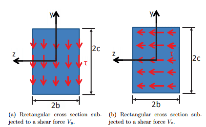
Figure 8.17: Schematic of a rectangular cross section subjected to a shear force along one direction
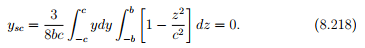
Next, we shall compute the y coordinate of the shear center ysc. Now, only shear force Vz should act. This shear force would be produced by loading along the xz plane, also a plane of symmetry for the cross section. This loading produces a shear stress as shown in figure 8.17b whose magnitude is again computed using (8.43) as
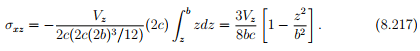
and σxy = 0. Substituting (8.217) in (8.214) we obtain
Thus, for the rectangular cross section, the shear center is located at the origin of the coordinate system, which in turn is the centroid of the cross section. Hence, the shear center coincides with the centroid of the cross section.
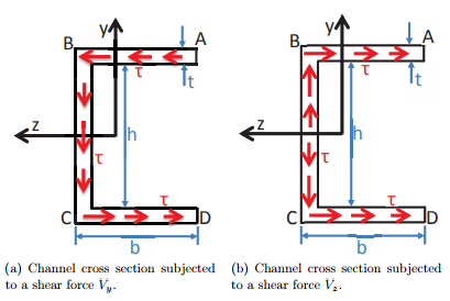
Figure 8.18: Schematic of a channel cross section subjected to a shear force along one direction
Example 2: Channel section
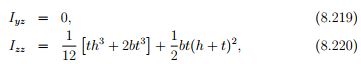
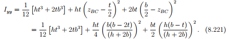
The next section that we study is the channel section with orientation and dimensions as shown in figure 8.18. The flange and web thickness of the channel is the same. Before proceeding to compute the shear center the other geometric properties, the centroid and the moment of inertia’s for the cross section is computed. The origin of the coordinate system being used is at the centroid of the cross section. Then, the distance from the centroid of the cross section to the top most fiber of the cross section AB is yAB = c = h/2 + t. Similarly, the distance of the left most fiber in the web of the cross section, BC is zBC = (ht + 2b2 )/(2(h + 2b)). Now,
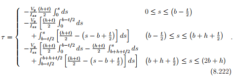
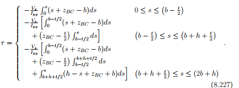
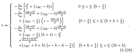
Towards computing the location of the shear center along the z direction, we first compute the shear stress acting on the cross section due to a shear force Vy alone. The magnitude of the shear stress, τ is found using (8.209) as
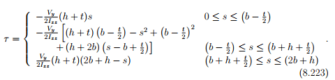
Evaluating the integrals and simplification yields,
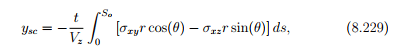
Since this shear stress has to be tangential to the cross section, it would be σxz component in the flanges and σxy component in the web. Rewriting equation (8.213) in terms of integration over the perimeter length,
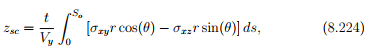
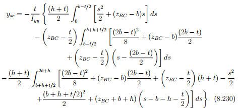
where So is the total length of the perimeter of the cross section. Evaluating the above equation, (8.224) for the channel section yields,
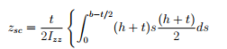
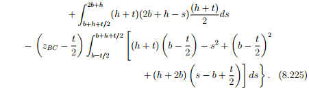
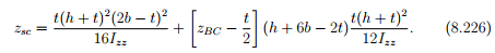
Evaluating the integrals in (8.225) and simplifying we obtain,
For computing the location of the shear center along the y direction, we For computing the location of the shear center along the y direction, we Vz alone. The magnitude of the shear stress, τ is found using (8.209) as
Integrating the above equation we obtain,
Since this shear stress has to be tangential to the cross section, as before, it would be σxz component in the flanges and σxy component in the web. Rewriting equation (8.214) in terms of integration over the perimeter length,
where So is the total length of perimeter of the cross section .Evaluation the above equation, (8.229) for the channel section yields,
Example 3: Circular arc
The final section that we use to illustrate the procedure to find the shear center is an arc of a circular section with radius R and a uniform thickness t. The arc is assumed to span from −(π − α) ≤ θ ≤ (π − α). Thus, it is symmetrical about the z direction. For convenience, we assume the origin of the coordinate system to be located at the center of the circle. First, we compute the centroid of the cross section
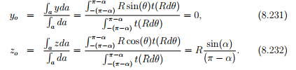
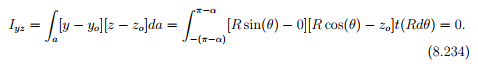
Here we have identified yo and zo with the coordinates of the centroid of the cross section, since it is homogeneous. Next, we compute the moment of inertias about the centroid,
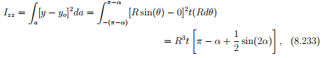
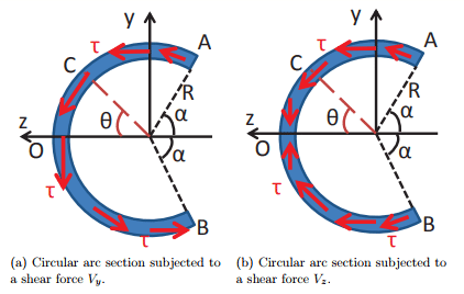
Figure 8.19: Schematic of a circular arc section subjected to a shear force along one direction
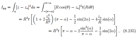
where the last equality is obtained on substituting for zo from (8.232). Towards computing the z coordinate of the shear center, we compute the shear stress distribution in the circular arc when only shear force Vy is acting on the cross section. The magnitude of the shear stress, τ is found using (8.208) as,
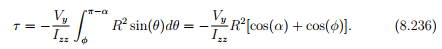
This shear stress would act tangential to the cross section at every location as indicated in figure 8.19a. Therefore, σxy = −τ cos(φ) and σxz = τ sin(φ), where φ is the angle the tangent makes with the y axis. Appealing to equation (8.213) we obtain,
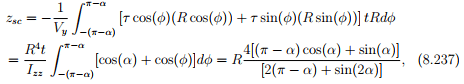
where we have used equations (8.236) and (8.233) respectively. It can be seen that when 0 < α ≤ π/2, zsc > 0 and in fact R < zsc ≤ 4R/π. Next, for computing the y coordinate of the shear center, we compute the shear stress distribution in the circular arc when only shear force Vz is acting on the cross section. The magnitude of the shear stress, τ is foundusing (8.208) as,
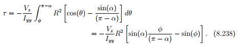
This shear stress would act tangential to the cross section at every location as indicated in figure 8.19b. Hence, as before, σxy = −τ cos(φ) and σxz = τ sin(φ), where φ is the angle the tangent makes with the y axis. Appealing to equation (8.214) we obtain,
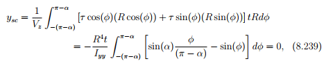
where we have used equations (8.238) and (8.235) respectively. Thus, the shear center is located along the z axis.
By virtue of the zsc being greater than R, the shear center is located outside the cross section. Hence, for the loading to pass through the shear center similar issues as discussed in the channel section exist.
FAQs on Shear Center - Civil Engineering (CE)
| 1. What is the shear center? |  |
| 2. Why is the shear center important in structural design? | |
| 3. How is the shear center different from the centroid? | |
| 4. How can the shear center be determined for a structure? | |
| 5. What are the consequences of not considering the shear center in structural design? | |


Shear Center - Civil Engineering (CE)
,practice quizzes
,Objective type Questions
,past year papers
,Exam
,Important questions
,MCQs
,study material
,mock tests for examination
,Viva Questions
,Summary
,video lectures
,Previous Year Questions with Solutions
,ppt
,Free
,Semester Notes
,Sample Paper
,Shear Center - Civil Engineering (CE)
,Extra Questions
,Shear Center - Civil Engineering (CE)
,shortcuts and tricks
;


Shear Center Free PDF Download
Importance of Shear Center
Shear Center Notes
Shear Center Civil Engineering (CE) Questions
Study Shear Center on the App
|
© EduRev
|
Education Revolution
|


|


within 7 days!