Shop Floor Control and FMS (Part - 5) - Mechanical Engineering PDF Download

Group Technology and Flexible Manufacturing Systems
Overview of Group Technology (GT)
- Parts in the medium production quantity range are usually made in batches
- Disadvantages of batch production
- Downtime for changeovers
- High inventory carrying costs
- GT minimizes these disadvantages by recognizing that although the parts are different, there are groups of parts that possess similarities
- GT exploits the part similarities by utilizing similar processes and tooling to produce them
- GT can be implemented by manual or automated techniques
- When automated, the term flexible manufacturing system is often applied
Group Technology Defined
- An approach to manufacturing in which similar parts are identified and grouped together in order to take advantage of their similarities in design and production
- Similarities among parts permit them to be classified into part families
- In each part family, processing steps are similar
- The improvement is typically achieved by organizing the production facilities into manufacturing cells that specialize in production of certain part families
Part Family
- A group of parts that possess similarities in geometric shape and size, or in the processing steps used in their manufacture
- Part families are a central feature of group technology
- There are always differences among parts in a family
- But the similarities are close enough that the parts can be grouped into the same family
Two parts that are identical in shape and size but quite different in manufacturing:
(a)1,000,000 units/yr, tolerance = ±0.010 inch, 1015 CR steel, nickel plate
(b)100/yr, tolerance = ±0.001 inch, 18-8 stainless steel
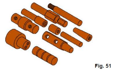
Ten parts those are different in size and shape, but quite similar in terms of manufacturing
- All parts are machined from cylindrical stock by turning; some parts require drilling and/or milling
Ways to Identify Part Families
1. Visual inspection - using best judgment to group parts into appropriate families, based on the parts or photos of the parts
2. Production flow analysis - using information contained on route sheets to classify parts
3. Parts classification and coding - identifying similarities and differences among parts and relating them by means of a coding scheme
Parts Classification and Coding
- Most classification and coding systems are one of the following
- Systems based on part design attributes
- Systems based on part manufacturing attributes
- Systems based on both design and manufacturing attributes
Part Design Attributes
- Major dimensions
- Basic external shape
- Basic internal shape
- Length/diameter ratio
- Material type
- Part function
- Tolerances
- Surface finish
Part Manufacturing Attributes
- Major process
- Operation sequence
- Batch size
- Annual production
- Machine tools
- Cutting tools
- Material type
Benefits of a Well-Designed Classification and Coding System
- Facilitates formation of part families
- Permits quick retrieval of part design drawings
- Reduces design duplication
- Promotes design standardization
- Improves cost estimating and cost accounting
- Facilitates NC part programming by allowing new parts to use the same part program as existing parts in the same family
- Computer-aided process planning (CAPP) becomes feasible
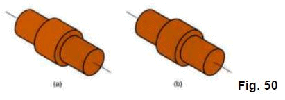
Composite Part Concept
- A composite part for a given family is a hypothetical part that includes all of the design and manufacturing attributes of the family
- In general, an individual part in the family will have some of the features of the family, but not all of them
- A production cell for the part family would consist of those machines required to make the composite part
- Such a cell would be able to produce any family member, by omitting operations corresponding to features not possessed by that part
- Composite part concept: (a) the composite part for a family of machined rotational parts, and (b) the individual features of the composite part
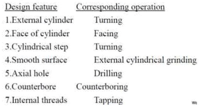
Composite Part Features and Corresponding Manufacturing Operations
Design feature Corresponding operation
Machine Cell Designs (Types of GT cells)
(a) Single machine
(b) Multiple machines with manual handling
(c) Multiple machines with mechanized handling
(d) Flexible manufacturing cell
(e) Flexible manufacturing system

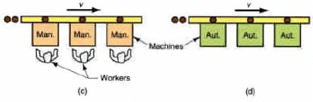
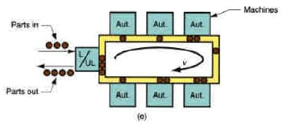
Fig. 52
Benefits of Group Technology
- Standardization of tooling, fixtures, and setups is encouraged
- Material handling is reduced
- Parts are moved within a machine cell rather than entire factory
- Process planning and production scheduling are simplified
- Work-in-process and manufacturing lead time are reduced
- Improved worker satisfaction in a GT cell
- Higher quality work
Problems in Group Technology
- Identifying the part families (the biggest problem)
- If the plant makes 10,000 different parts, reviewing all of the part drawings and grouping the parts into families is a substantial task
- Rearranging production machines in the plant into the appropriate machine cells
- It takes time to plan and accomplish this rearrangement, and the machines are not producing during the changeover
FMS Planning and Design Issues
- Part family considerations
- Defining the part family of families to be processed
- Based on part similarity
- Based on product commonality
- Defining the part family of families to be processed
- Processing requirements
- Determine types of processing equipment required
- Physical characteristics of workparts
- Size and weight determine size of processing equipment and material handling equipment
- Production volume
- Annual quantities determined number of machines required
- Types of workstations
- Variations in process routings
- Work-in-process and storage capacity
- Tooling
- Pallet fixtures
FMS Operational Issues
- Scheduling and dispatching
- Launching parts into the system at appropriate times
- Machine loading
- Deciding what operations and associated tooling at each workstation
- Part routing
- Selecting routes to be followed by each part
- Part grouping
- Which parts should be on the system at one time
- Tool management
- When to change tools
- Pallet and fixture allocation
- Limits on fixture types may limit part types that can be processed
Flexible Manufacturing System: Overview
- A highly automated GT machine cell, consisting of a group of processing stations (usually CNC machine tools), interconnected by an automated material handling and storage system, and controlled by an integrated computer system
- The FMS relies on the principles of GT
- No manufacturing system can produce an unlimited range of products
- An FMS is capable of producing a single part family or a limited range of part families
Flexibility Tests in an Automated Manufacturing System
- Automated manufacturing cell with two machine tools and robot. Is it a flexible cell?
- To qualify as being flexible, a manufacturing system should satisfy the following criteria (“yes” answer for each question):
1. Can it process different part styles in a non-batch mode?
2. Can it accept changes in production schedule?
3. Can it respond gracefully to equipment malfunctions and breakdowns?
4. Can it accommodate introduction of new part designs?
If the automated system does not meet these four tests, it should not be classified as a flexible manufacturing or cell.
Is the Robotic Work Cell Flexible?
1. Can it machine different part configurations in a mix rather than in batches?
2. Can production schedule and part mix be changed?
3. Can it operate if one machine breaks down?
Example: while repairs are being made on the broken machine, can its work be temporarily reassigned to the other machine?
4. As new part designs are developed, can NC part programs be written off-line and then downloaded to the system for execution?
This fourth capability also requires that the toolings in the CNC machines as well as the end effecter of the robot are suited to the new part design.
FMS Components
- Hardware components
Workstations - CNC machines in a machining type system
Material handling system - means by which parts are moved between stations
Central control computer - to coordinate the activities of the components so as to
achieve a smooth overall operation of the system
- Software and control functions
- Human labor
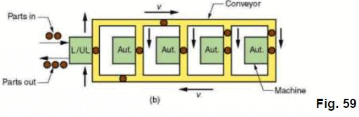
Five Types of FMS Layouts
1. In-line
2. Loop
3. Ladder
4. Open field
5. Robot-centered cell
- The basic layout of the FMS is established by the material handling system
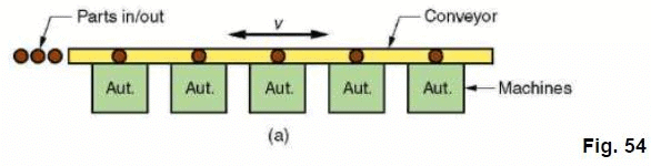
Three of the five FMS layout types: (a) in-line
Key: Aut = automated station; L/UL = load/unload station;
Insp = inspection station; AGV = automated guided vehicle;
AGVS = automated guided vehicle system
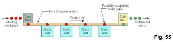
- Straight line flow, well-defined processing sequence similar for all work units
- Work flow is from left to right through the same workstations
- No secondary handling system
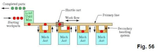
- Linear transfer system with secondary parts handling system at each workstation to facilitate flow in two directions
Loop layout
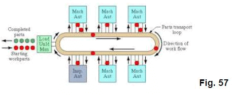
- One direction flow, but variations in processing sequence possible for different part types
- Secondary handling system at each workstation
Rectangular Layout
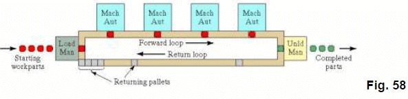
- Rectangular layout allows recirculation of pallets back to the first station in the sequence after unloading at the final station
Ladder layout
Key: Aut = automated station; L/UL = load/unload station;
Insp = inspection station; AGV = automated guided vehicle;
AGVS = automated guided vehicle system
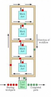
Fig. 60
- Loop with rungs to allow greater variation in processing sequence
Open field
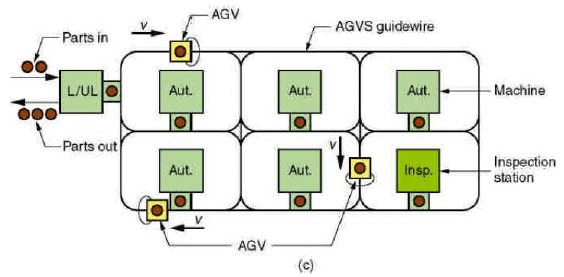
Fig. 61
- Key: Aut = automated station; L/UL = load/unload station;
Insp = inspection station; AGV = automated guided vehicle; AGVS = automated guided
vehicle system
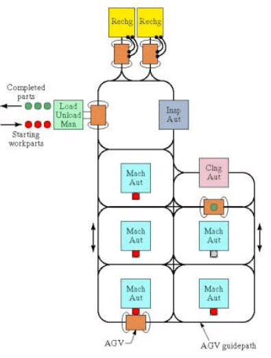
Fig. 62
- Multiple loops and ladders, suitable for large part families
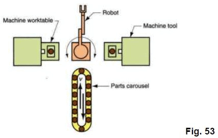
Robot centered layout
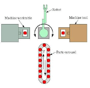
Fig. 63
- Suited to the handling of rotational parts and turning operations
FAQs on Shop Floor Control and FMS (Part - 5) - Mechanical Engineering
| 1. What is shop floor control? |  |
| 2. What is FMS (Flexible Manufacturing System)? | |
| 3. How does shop floor control improve productivity? | |
| 4. What are the benefits of implementing FMS? | |
| 5. How does FMS contribute to cost reduction? | |


Summary
,study material
,Previous Year Questions with Solutions
,video lectures
,Shop Floor Control and FMS (Part - 5) - Mechanical Engineering
,MCQs
,Exam
,Shop Floor Control and FMS (Part - 5) - Mechanical Engineering
,shortcuts and tricks
,practice quizzes
,Important questions
,Shop Floor Control and FMS (Part - 5) - Mechanical Engineering
,past year papers
,Objective type Questions
,Free
,ppt
,Sample Paper
,Extra Questions
,mock tests for examination
,Semester Notes
,Viva Questions
;


Shop Floor Control and FMS (Part - 5) Free PDF Download
Importance of Shop Floor Control and FMS (Part - 5)
Shop Floor Control and FMS (Part - 5) Notes
Shop Floor Control and FMS (Part - 5) Mechanical Engineering Questions
Study Shop Floor Control and FMS (Part - 5) on the App
|
© EduRev
|
Education Revolution
|


|


