Short Notes: Symmetrical Components | Power Systems - Electrical Engineering (EE) PDF Download
Introduction
In power systems, it is a common occurrence that there are unbalanced voltages and currents on the distribution side of the grid. But these voltages and currents might be unbalanced anywhere through the grid in the case of a Fault, most commonly a short circuit fault. The simplest method to calculate the before mentioned quantities is a method termed "symmetrical per phase" technique and the concept is known as Symmetrical Components given by Fortescue's Theorem. It is also known as the "Three-component method". It can be descried as:
An unbalanced system of 'n' phasors can be resolved in an 'n' system of balanced phasors called the symmetrical components of the original system.
What are symmetrical components and Why do we use them?
An unbalanced system consisting of ‘n’ number of phasors can be divided into ‘n’ systems of balanced phasor. These ‘n’ systems of balanced systems are known as symmetrical components.
Under the unbalanced condition, it is imperative to calculate the magnitude and phase angles of voltages and currents of each of the phases of the concerned section of the grid, as the protection system Relays use these values as the basic parameters for operation. But this can be quite a tedious and difficult task as the system is quite large and unbalanced values also tend to make the calculations complex.
The method of symmetrical components simplified the problem of three-phase unbalanced systems. Symmetrical components, besides, to be a powerful analytical tool, is also conceptually useful. The symmetrical components themselves, which are obtained from a transformation of the ordinary line voltages and currents, are useful. Symmetrical components have become accepted as one way of describing the properties of many types of network elements such as transmission lines, motors, and generators.
Balanced Three Phase System
A balanced 3 phase system is one in which each voltage or current phases are equal in magnitude and the three phases are 120 degrees apart in phase angles.

So, what is the balanced set of phasors? Well, its like a spinning wheel with three arrows. Let's name the three arrows A, B, and C. For 3-phase balanced set the angle between the phasors is of 120' and has the same magnitude. The three arrows (phases) are 120' apart. The wheel can rotate in two possible directions counter-clockwise and clockwise. Now depending on how the wheel rotates the arrows(Phases) will have the sequence of ABC or ACB. This is seen by considering a stationary point if the wheel rotates clockwise first A will pass the point then C and then B. And when the wheel rotates counterclockwise then A will come first then B and finally C. These are the angle, magnitude and phase sequence relation of Balanced set of Phasors.
Balanced vs Unbalanced Phasors
There is a major difference in balanced and unbalanced phasors. The balanced or symmetrical set of phasors are those which have the same magnitude and are all 120' apart. Whereas the unbalanced or unsymmetrical set of phasors are those that have at least 1 phase having 1 magnitude not similar to the others or 1 phase being apart at an angle that is not 120'.
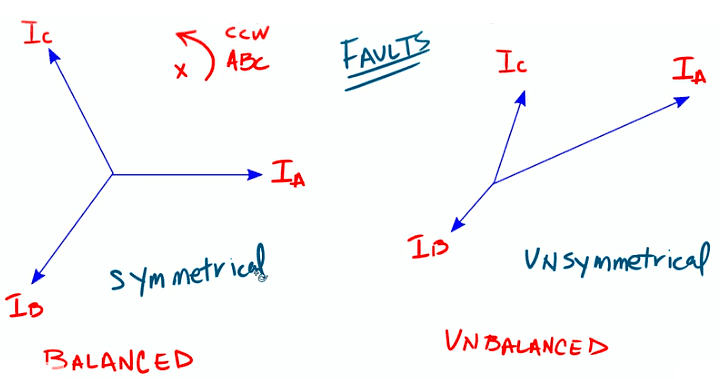
Breakdown of the Symmetrical Components
As the name three-component method suggests that the symmetrical components comprise a set of components that are balanced in nature.
- Positive sequence component
- Negative sequence component
- Zero sequence component
For a symmetrical system, the source(generator) currents are equal in magnitude and are in phase, with their three phases 120" apart. Also, the impedances of the three-phase circuits and equipment are of equal magnitude and phase angle.
Consider an unbalanced current phasor system shown in the figure below. Suppose that the phasors are represented by Ia,Ib and Ic and their phase sequence is Ia,Ib,Ic. The phase sequence of the positive component is Ia,Ib,Ic and the phase sequence of negative components is Ia,Ic,Ib.
Positive Sequence Component
For a the positive sequence the Three phasors are balanced. Meaning their magnitude is same and they are 120' apart. They have the same phase sequence as that of the original set of phasors. For this case it is Ia,Ib,Ic. They are as shown in figure below: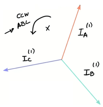
Negative Sequence Component
For a negative sequence the Three phasors are balanced. Meaning their magnitude is same and they are 120’ apart. They have the opposite phase sequence as that of the original set of phasors. For this case it is Ia,Ic,Ib. They are as shown in figure below: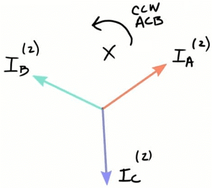
Zero Sequence Component
The zero phase sequence components are the set of three phasors that are equal in magnitude and at zero phase displacement from each other. The zero-phase sequence component is as shown in the figure below.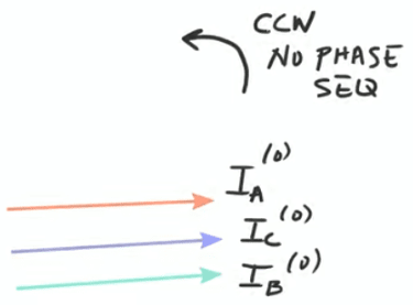

Operator 'a'
As we have seen that in symmetrical component theory the concept of 120º displacement is quite important therefore, we require some parameter or operator that might cause this 120' rotation. The operator 'a' is thus used. It is defined as under:
The 'a' operator is a unit vector at an angle of 120 o. It can be written as:
a=1∠120∘
a2=1∠240∘
Multiplying by 'a' will have the effect of rotating any phasor by 120˚. And multiplying by a2 will rotate the phasor by 240˚.
Mathematical Equations of Symmetrical Components
The unbalanced phase currents in a 3-phase system can be expressed in terms of symmetrical components as under: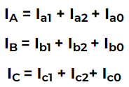
Where,
The subscript 1 represents positive sequence component of each phase.(Ia1 for phase A)
The subscript 2 shows negative sequence component of each phase.(Ia2 for phase A)
And subscript 0 shows the zero-sequence component of each phase(Ia3 for phase A)
In order to simplify our calculations, we will be using phasor A as our reference phasor.
Positive Sequence Components
We will now be using the 'a' operator to relate the positive sequence components of each phase.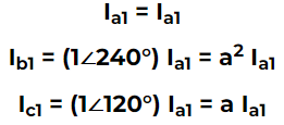
So, it can be seen here that positive sequence components of phase ‘B’ and phase ‘C’ are ‘a2’ and ‘a’ times the positive sequence component of phase ‘A’. Hence a set of balanced positive sequence currents is achieved.
Negative sequence Components
We will now be using the 'a' operator to relate the negative sequence components of each phase.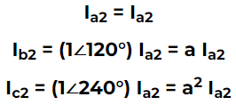
It can also be seen here that negative sequence components of phase 'B' and phase 'C' are 'a' and 'a2' times the negative sequence component of phase 'A'. Hence a set of balanced negative sequence currents is achieved.
Zero sequence Components
It should be noted that zero sequence components for each phase remain the same.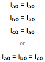 A balanced set of zero sequence components is achieved here.
Simplified Equations
We can now substitute the symmetrical components of each phase with their equivalent to the reference phase A to get a set of equations completely in terms of phase A components.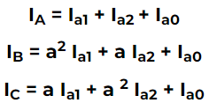
Hence all our 3 phasors can be represented using symmetrical components of only phase 'A'.
We can also manipulate these equations to get a set of equations which will give us the symmetrical components of Phase ‘A’ , Ia1, Ia2, Ia0, in terms of the other phasers IA, IB, IC.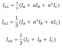
Hence with these equations, we can convert an unbalanced system into a balanced set of 3 systems.
Moreover, we can convert symmetrical components into their respective phasors and vice versa with these equations.
It is also important to note that the same equations apply for Voltages as well. We just replace 'I' with 'V'.
Where VA ,VB and VC are the phasor voltages, and Va1 , Va2, and Va0 are the positive, negative and zero sequence Voltages of Phase 'A'.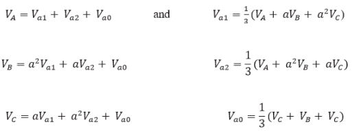
Importance of symmetrical components
We can see those symmetrical components are a way of analyzing unbalanced phasors which arise due to faults. Converting a set of unbalanced phasors into sets of balanced components greatly simplifies our analysis and is helpful in performing fault calculations, power flow studies, and stability studies.
Along with phasor values of current and voltage, the zero-sequence and negative sequence components are also an important input to protective relays that sense these values to decide the nature and type of the fault.
For example, a zero-sequence component indicates a ground fault, while unbalanced loading leads to negative components, hence sensing these components is essential in order to efficiently protect our power system.
Moreover, we can calculate sequence impedances using symmetrical components, from which we can derive sequence circuits of transmission lines and transformers and ultimately sequence networks of a complete power system. This helps us analyze the behavior of our power system under different types of faults.
Symmetrical components are a powerful tool for the analysis of unbalanced components in the power system and useful for studying the behavior of systems during faults. Check out Power System Protection Fundamentals Course in which we briefly discussed "Principles of Symmetrical Components".
|
21 videos|67 docs|45 tests
|

|
Explore Courses for Electrical Engineering (EE) exam
|

|


