Stability of Feedback Control System - Electrical Engineering (EE) PDF Download

Stability of feedback control system
Frequency response analysis is an useful tool for designing feedback controllers. It enables the designer to study the stability characteristics of a closed loop system using Bode or Nyquist plots and also to select the appropriate design values of controller parameters.
Bode Diagram of closed loop process
Bode diagram of PID controler
It is also worth to study the Bode diagram of PID controller in the following figure.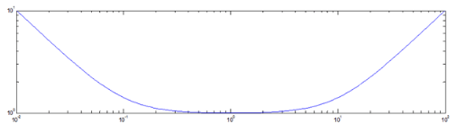
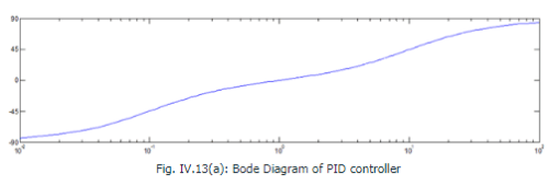
The PID controllers have the following characteristics: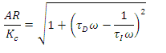
And
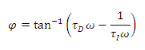
It is left to the reader to exercise how to arrive at above eqs. Note that the PID controllers ideally have three asymptotes.
• 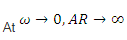 with a (-1) slope
• 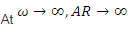 with a slope (1+)
• 

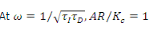 with a zero slope.
Bode diagram of Processes in series
Let us have a control loop with two components, viz ., one PI controller and one first order plus dead time model.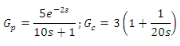
The open loop transfer function is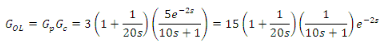
The above open loop transfer function is a combination of four individual processes in series, viz., pure gain, pure dead time, first order system and PI controller. Two time constants are observed in the series that would yield the location of corner frequencies viz ., 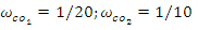 or
or 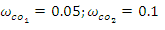
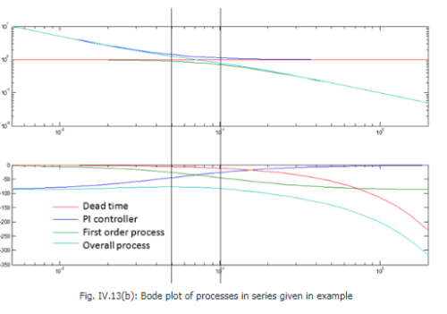
The above figure shows the Bode plot of the open loop process indicated in this example. AR and phase shift for all individual transfer functions as well as the overall transfer function have been indicated along with the location of corner frequencies.
Bode Stability Criterion
Consider a simple first order plus dead time process to be controlled by a proportional controller: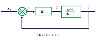
Example of first order system for studying Bode stability criterion
The open-loop transfer function for this system is given by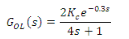 71
71
The Bode plot of the above open loop transfer function is given by the following figure.
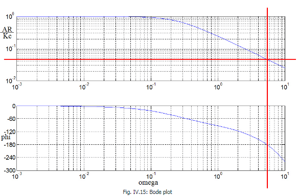
We are interested to know the frequency where the phase shift is -1800. Numerically it can be solved by the equation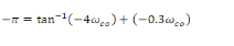 72
72
The frequency is  and the value of AR/2Kc at
  is observed to be 0.0463 which can also be found numerically by,
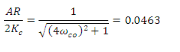 73
73
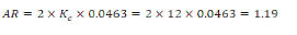
The above exercise indicates that in order to obtain AR = 1 at this frequency  one needs to set the value of Kc as,
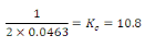 74
74
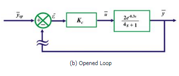
At this juncture, one needs to perform a thought experiment in order to understand the Bode stability criterion. Let us set the value of controller gain, Kc = 10.8 and let us “open up” the feedback loop as indicated in the figure before. Suppose, we vary the setpoint as a sinusoidal function 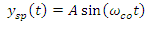 . As the loop is open, the error will be equal to the setpoint
 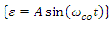 and thereby yield an output,
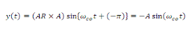 75
75
Now, suppose two events occur simultaneously
• The setpoint perturbation is stopped
• The feedback loop is reconnected
Then, the error signal will remain as 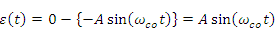 . In other words, the response of the system will continue to oscillate with constant amplitude even when the setpoint signal is withdrawn.
Alternatively, if we choose the value of controller gain less than 10.8 , (say Kc = 8) then
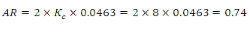 76
76
If we repeat the above thought experiment, the output signal will take the form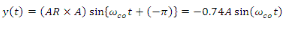 77
77
Upon closing the loop and withdrawing the setpoint perturbation, the new value for the error for the next cycle will be 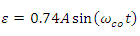 that will eventually yield an output response of
 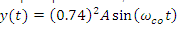 and so on. It is evident that the amplitude of the error signal would diminish at every cycle and eventually lead to zero.
In case we choose the value of controller gain greater than 10.8 , (say Kc = 12) then
 78
78
The same thought experiment would lead to ever increasing error signal because the amplitude ratio is greater than 1.
Hence the above thought experiment indicates that we have been able to find a combination of frequency  and controller gain
  such that the AR of the process becomes 1 and phase shift becomes -1800 simultaneously at that combination
  . The output response shows a sustained oscillation with a time period
  at this combination. Any frequency,
  , will lead to oscillation with increasing amplitude and eventually will lead to instability. Hence, the frequency
  is termed as the crossover frequency , the gain value Ku is termed as ultimate gain and Pu is called the ultimate period of oscillation of the closed loop system.
The conclusion drawn from the above thought experiment is the Bode Stability Criterion and can be stated as follows -A feedback control system is unstable if the amplitude ratio of the corresponding open loop transfer function is greater than one at the crossover frequency. The value of controller gain is the decisive factor in order to ensure its stability.
It is further understood from eq. (72) that large dead time leads to smaller value crossover frequency. In other words, even a low frequency signal will be able to destabilize such process.
FAQs on Stability of Feedback Control System - Electrical Engineering (EE)
| 1. What is stability in a feedback control system? |  |
| 2. How is stability analyzed in a feedback control system? | |
| 3. What are the types of stability in a feedback control system? | |
| 4. How does feedback control improve system stability? | |
| 5. What are the consequences of an unstable feedback control system? | |


mock tests for examination
,past year papers
,Stability of Feedback Control System - Electrical Engineering (EE)
,Sample Paper
,Semester Notes
,Objective type Questions
,video lectures
,Extra Questions
,ppt
,Stability of Feedback Control System - Electrical Engineering (EE)
,Exam
,practice quizzes
,study material
,MCQs
,shortcuts and tricks
,Stability of Feedback Control System - Electrical Engineering (EE)
,Viva Questions
,Important questions
,Free
,Previous Year Questions with Solutions
,Summary
;


Stability of Feedback Control System Free PDF Download
Importance of Stability of Feedback Control System
Stability of Feedback Control System Notes
Stability of Feedback Control System Electrical Engineering (EE) Questions
Study Stability of Feedback Control System on the App
|
© EduRev
|
Education Revolution
|


|


