Study Notes: Antennas | Electromagnetics - Electronics and Communication Engineering (ECE) PDF Download
| Table of contents |

|
| Introduction |

|
| Dipole Antenna |

|
| Key Points |

|
| Practical Antenna |

|
| Log-Periodic Antenna |

|
| Reflector Antenna |

|
Introduction
An antenna is a way for linking the electromagnetic waves from transmitter to receiver.
A resonant antenna is a transmission line whose length is exactly equal to the multiple of half wavelength, i.e.,
l = nλ/2
where, n = 1, 2, 3,….. positive real integer and λ is wavelength.
Basic Antenna Parameters: Antenna parameters are the factors that select the antenna for particular reason or application.
Directivity: Directivity is defined as the ratio of radiation intensity in particular direction to average radiation intensity
- U(θ, φ) = radiation intensity in a direction
- Uav = average radiation intensity
Dipole Antenna
- A dipole antenna may be defined as a symmetrical antenna in which the two ends are at equal potential relative to mid-point.
- A physical dipole consists of two equal and opposite charges i.e., in the literal sense, two poles.
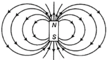
- The dipole magnetic field lines are shown in the figure.
- A half-wave dipole λ/2 antenna is the fundamental ratio antenna of the metal rod on a thin wire, which has a physical length of half wavelength in free space.
 Dipole magnetic field antenna linesNote: A λ/2 antenna is also known as Hertz antenna or half-wave doublet.
Antenna's Power and Field: Normalized power and field pattern can be obtained by dividing a power or field component by its maximum value respectively i.e.,
Normalized power:

Normalized field pattern:
- Radian is defined as the arc of length l on the circle from a centre of the circle of radius r since the circumference of a circle is 2πr, there are 2π radians in a full circle.
- Area of a sphere is 4πr2, there is 4π steradian in a full sphere i.e., dω = 4π.
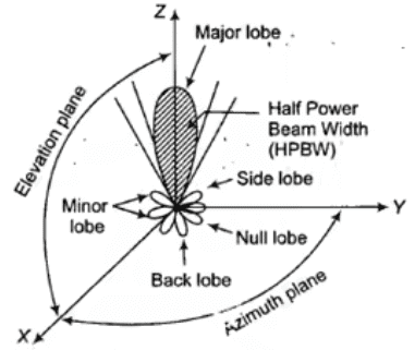
Radiation Pattern: The radiation pattern is basically a 3-D graph which indicates the variations in electromagnetic field or power as a function of spherical coordinates θ and φ.
Field pattern: Following Figure shows the radiation pattern of an antenna which includes generally three lobes as a main lobe, side lobe, and back lobe.
Main lobe: It contains the direction of maximum radiation.
Side lobe: The side lobe is adjacent to the main lobe.
Back lobe: In back lobe, the field goes to zero. Field pattern of an antenna
Key Points
- The radiation pattern is different for different antennas and is affected by the location of an antenna with respect to earth.
- When radiation pattern is measured in terms of field strength E then it is called field strength pattern.
- When it is measured in terms of power unit solid angle, then it is called as power pattern.
- The field pattern and power pattern are related to each other.
Radiation Intensity: radiation intensity is defined as the radiated power per unit solid angle i.e.,
Radiation intensity(in watt/steradian):
U = Wr/4π
where Wr = Radiated power
Antenna Characteristics: The following are the basic parameters of an antenna which judge the characteristics of an antenna
- Antenna efficiency:
η = Power radiated/Total power input = Pr/PT - Directivity:
D = Maximum radiation intensity of test antenna/Average radiation intensity of test antenna = U (θ, ∅)max/Uav - Directivity, in terms of power and solid angle,

(Beam solid angle or beam area) - For isotropic antenna:

where, U0 = Radiation intensity of the isotropic antenna - In terms of beam area:

- Gain of antenna can be related to directivity as G = kD; where, k = Efficiency factor (0 ≤ k ≤ 1
- The ratio of maximum radiation intensity in a given direction to the maximum radiation intensity from a reference antenna produced in the same direction with same power input:
G0 = Um/U0
where, Um = maximum radiation intensity in a given direction and U0 = maximum radiation intensity from a reference antenna - Power gain: The power gain compares the radiated power density of actual antenna and an isotropic antenna on the basis of same input power o both:

where PT = Transmitted power - Directive gain: The directivity gain in a given direction is defined as the ratio of the radiation intensity in that direction to the average radiated power:

where Pr = radiated power - Power gain and directive gain can be related as GP = ηGd
- In a case of directivity gain, the total output power is maintained same.
- In the case of power gain, the total input power is maintained the same.
Effective Area:
Ae = Power received/ Power density of incident wave (W/m2 = Pr/S
- It is also called antenna aperture.
Effective Height: The effective height of an antenna indicates that how effectively an antenna radiates or receives an electromagnetic wave energy.
h = Induced voltage (V)/Incident field (E)
- Relation between him and Ae

where Z0 = Intrinsic impedance = 377Ω - Antenna aperture efficiency (εap) for horn and parabolic antenna is in the range of 50% to 80%.
Beam Efficiency (εm): The beam efficiency is defined as the ratio of power transmitted with in cone angle (θ) to the power transmitted by the antenna. In terms of beam area (ΩA)
εm = Ωm/ΩA = main beam area/Total beam area
- The resolution of an antenna is defined as equal to half the beam width between the first nulls.
- Resolution =
FNBW/2
where, FNBW ≅ 2 HPBW; HPBW = Half Power Beam Width; FNBW = Full Null Beam Width
- Antenna beam area:

- Directivity is equal to the number of point sources in the sky that the antenna can resolve.
- Radiation in the dipole occurs due to moving charge in simple harmonic motion along the conductor i.e., acceleration or deceleration of charge along the conductor.
Antenna Beam Width: Antenna beam width is defined as the angular separation between two half power points on the radiation pattern of an antenna.
Practical Antenna
Although any circuit can radiate if driven with a signal of high enough frequency, most practical antennas are specially designed to radiate efficiently at a particular frequency.One of the goals of antenna design is to minimize the reactance of the device so that it appears as a resistive load.
- RMS value of induced emf in loop antenna having N turns in volts is

- The far-field of the loop has only an Eφ component and Hθ component as,

Log-Periodic Antenna
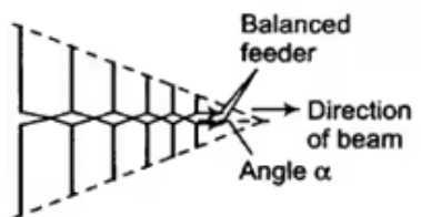
A log-periodic antenna is a broadband, multi-element, directional, narrow-beam antenna that has impedance and radiation characteristics that are regularly repetitive as a logarithmic function of the excitation frequency.In a log-periodic antenna, the design ratio (τ) or scale factor can also be written as
where, R = Spacing between dipoles, L = Length of the dipole and Apex angle is
 Log - periodic antenna
- In helical antenna, the pitch angle can be calculated as

where, πD is the circumference of the helix, S is the spacing of the helix. If the pitch angle is zero, then the winding is flattened. In horn antenna, the flare angle can be calculated as

where a = Aperture of the horn in the horn antenna
L = Horn length in metre
S = Path length in the front face of the horn
and
- Optimum horn dimensions can be related by
Optimum S,
Optimum length,
- In the horn antenna, the value of S in E plane is usually 0.25 λ and in H plane is usually 0.4 λ.
- Directivity of a horn antenna can be expressed in terms of its effective aperture is

- For rectangular horn, the value of directivity is

- For pyramidal (rectangular) horn, the value of directivity can also be expressed as D ≅ 10 logs (7.5 aελ aHλ)
- In microstrip antenna, the characteristic impedance is
 Zc = 26.7Ω
where, Z0 = intrinsic impedance
η = w/t (width of the microstrip)/(Thickness of the microstrip)

- Maximum effective aperture of the loop in loop antenna is
Aem = 3λ2/8π - The expression for radiation resistance in the loop antenna is:
Rr = 3720(α/λ)
where a = Radius of the loop (circular)
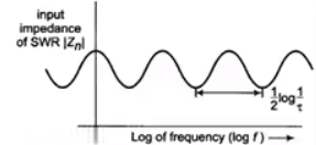
Input Impedance versus Log f Plot: Figure below shows a plot of input impedance |Zin| versus the logarithm of frequency.
The impedance |Zin| goes through identical cycles of variations where each cycle is exactly like the preceding one.
- In helical antenna, BWFN (Beam Width of First Null)

where, C = Circumference = πD, La = Total length of the helical antenna
- Directivity:
D = 15NC2S/λ3
where, S = Spacing between turns, N = Number of turns, λ = Wavelength, and C = Circumference of the helix.
Reflector Antenna
The antennas which used for microwave frequency regions are called parabolic reflector antennas. Parabolic dish antennas are liked to generate narrow beams in the microwave region. Reflectors are used to adjust the radiation of the primary antenna and increase the directivity in any particular direction.- Half power beam width of paraboloid is
∅ = 70λ/Dα - Directivity of the paraboloid is
D = 9.87(D/λ)2 - Power gain of the paraboloid is
gp = 6.4(Da/λ)2 - Reflectors are used to produce desired shapes of the radiation pattern.
- A flat sheet reflector is the simplest reflector or which is used to guide electromagnetic energy in the desired direction.
- A corner reflector is a reflective object which consists of two or three mutually intersecting conducting flat surfaces.
- A reflector which has the directional feed which radiates all or most of the energy into parabola is called parabolic reflector.
- For flat sheet reflector, the gain and the spacing of the drive unit can be related as

where S is the spacing of antenna from the flat sheet reflector. - Offset feed is used to removing the problem of aperture blocking in the parabolic reflector.
- In corner reflector, a spacing of driven element modulates the bandwidth and gain of the main lobe.
- A cylindrical parabola converts a cylindrical wave radiated by an in-phase line source at the focus into a plane wave at the aperture.
- For rectangular aperture paraboloidal reflector, Beam Width First Null is given by BWFN
= 115λ/L
degree - Due to the tapering in paraboloid reflector, the captured area is less as compare to actual area i.e., A0 = k Aa
- where A0 is capture area and Aa is the actual area of the mouth and k is constant whose value is 0.65 for a dipole antenna.
- The phases of all waves arriving at the aperture are the same i.e., a plane wave front is created in the aperture plane.
- In the parabolic reflector, all the waves are in phase, a very strong and concentrated beam of radiation is along the parabolic axis.
- The geometrical properties of a parabola provide very good microwave reflectors that lead to the generation of concentrated beam of radiation.
- Aperture and directivity can be related as
D = 4πAe/λ2 - Beam width between the first null for large circular aperture is (in degree)
VWFN = 140λ/d - Far field or Fraunhofer region can be expressed as (in metre)
df = 2D2/λ - Near field, a region is a region close to the transmitter, in some λ distance and the far field region is far away from the transmitter, after some λ distance.
- The height of the transmitting antenna and Antenna Under Test (AUT) can be related as
HAUT = λ.D/4Hr
where D is the distance between source and AUT. - Indoor measurement is controlled and interference free, so easy and accurate.
- For accurate measurement of far-field or Fraunhofer region, the distance between transmitting and receiving antenna should be
r ≥ 2d2/λ
where d is a maximum linear dimension of the aperture of either antenna. - Gain and directivity can be related as
D = G0/λ - In two antenna, absolute gain measurement, the gain can be expressed as

where PR = Receiving power, and PT = Transmitting power
|
11 videos|94 docs|89 tests
|
FAQs on Study Notes: Antennas - Electromagnetics - Electronics and Communication Engineering (ECE)
| 1. What is a dipole antenna? |  |
| 2. What are the key points to consider when selecting an antenna? |  |
| 3. What is a log-periodic antenna? |  |
| 4. How does a reflector antenna work? |  |
| 5. What are practical antennas? |  |


