Study Notes For Three Phase AC Circuit | Network Theory (Electric Circuits) - Electrical Engineering (EE) PDF Download
- Phase is applied to the periodic changes of some quantity, such as the voltage in an AC circuit.
- Electrical phase is measured in degrees, with 360° corresponding to a complete cycle.
- A sinusoidal voltage is proportional to the cosine or sine of the phase.
- Three-phase, abbreviated 3φ, refers to three voltages or currents.
- It is a system produced by a generator consisting of three sources having the same amplitude and frequency but out of phase with each other by 120°.
- The three phases could be supplied over six wires, with two wires reserved for the exclusive use of each phase. However, they are generally supplied over only three wires, and the phase or line voltages are the voltages between the three possible pairs of wires.
- The phase or line currents are the currents in each wire.
- Voltages and currents are usually expressed as RMS or effective values, as in single-phase analysis.
Following requirements must be satisfied in order for a set of 3 sinusoidal variables (usually voltages or currents) to be a "balanced 3-phase set"
- All 3 variables have the same amplitude
- All 3 variables have the same frequency
- All 3 variables are 120o in phase
Following requirements must be satisfied in order for a 3-phase system or circuit to be balanced.
- All 3 sources are represented by a set of balanced 3-phase variables
- All loads are 3-phase with equal impedances
- Line impedances are equal in all 3 phases
Advantages of 3 Phase Circuits:
- Most of the electric power is generated and distributed in three phase.
- The instantaneous power in a three-phase system can be constant.
- The amount of wire required for a three-phase system is less than that required for an equivalent single-phase system.
- For the same amount of power, the three-phase system is more economical that the single-phase.
Three Phase Circuit Connections: There are two basic schemes for connecting a load or generator in a three-phase circuit.
- The Y or "wye" connection joins neutrals of each phase at a common junction.
- The Δ or "delta" connection is a triangle whose vertices form the buses, and there is no neutral bus.
Star or “Y” (also known as the “T”) configuration: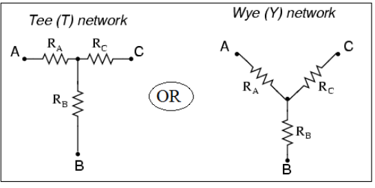
- The wye or star connection is made by connecting one end of each of the three-phase windings together as shown in the above figure.
- The voltage measured across a single winding or phase is known as the phase voltage.
- The voltage measured between the lines is known as the line-to-line voltage or simply as the line voltage.
- In a wye connected system, the line voltage is higher than the phase voltage by a factor of the square root of 3.
- In a wye connected system, phase current and line current are the same.
Delta, or Δ (also known as the “Pi,” or π) configuration:
- In a delta connection, line voltage and phase voltage are the same.
- The line current of a delta connection is higher than the phase current by a factor of the square root of 3
Balanced Three‐Phase Connections: Four possible connections between source and load.
- Y-Y connection (Y-connected source with a Y-connected load)
- Y-∆ connection (Y-connected source with a ∆-connected load)
- ∆-∆ connection
- ∆-Y connection
Wye‐Delta transformation
- Wye-Delta transformation is also called as start-delta transformation.
- Wye-Delta Transformation is a technique to reduce common resistor connections that are neither series nor parallel.
- Conversion from Delta (Δ) to Wye (Y)
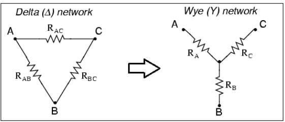
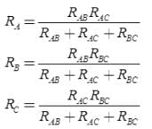
- Conversion from Wye (Y) to Delta (Δ)
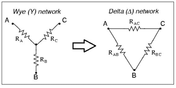
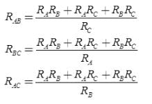
Transformations
- Star-Delta Transformation
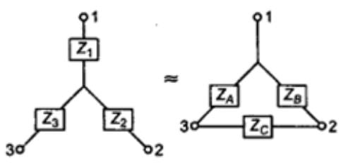
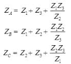
- Delta-Star Transformation
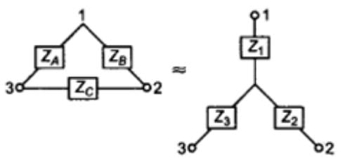
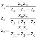
Note: Both Star Delta Transformation and Delta Star Transformation allows us to convert one type of circuit connection into another type in order for us to easily analyse the circuit. These transformation techniques can be used to good effect for either star or delta circuits containing resistances or impedances.
Example-1: Compute the total resistance between A and B terminals in the following network circuit.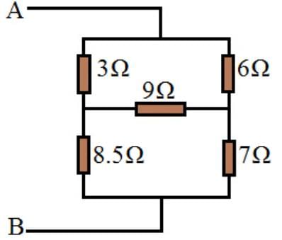
Using the Delta to star transformation, the following network in between 1,2,and 3 points converted.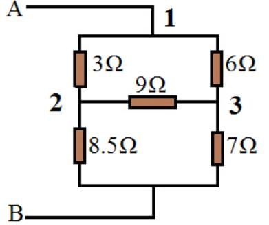
Delta to star transformation equations:
(i) R1 = R12R31 / (R12+R23+R31)
R1 = (3*6)/ (3+6+9) = 1Ω
(ii) R2 = R23R12 / (R12+R23+R31)
R2 = (9*3)/18 = 1.5Ω
(iii) R3 = R31R23 / (R12+R23+R31)
R3 = (6*9)/18 = 3Ω

Now, it is easy to compute the total resistance between points A and B.
RAB = (7Ω+3Ω) + (8.5Ω+1.5Ω) + 1Ω = 6Ω.
Example-2: Compute the total resistance between A and B terminals in the following network circuit.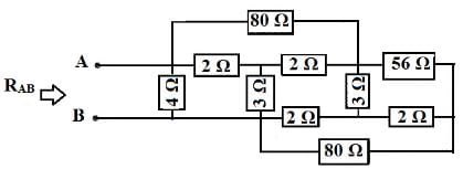
Solution: In the above circuit, identify the star connections (Y) which is shown with circles in the following circuits.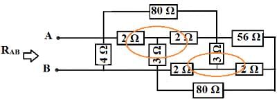
Star to Delta Transformation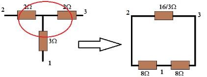
Similarly other circle can also be converted from star to delta as included in the following circuit.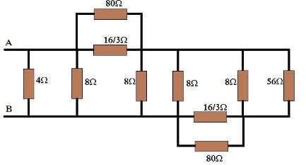
It is simple to convert two parallel connections of above circuit into the below circuit.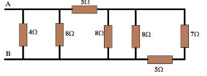
RAB = {[(7+5) || 8 || 8] + 5} || 8 || 4 RAB = (3 + 5) || 8 || 4 RAB = 4 || 4 RAB = 2Ω
Delta-Star and Star-Delta Transformation
- Star-Delta
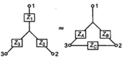
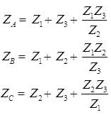
- Delta-Star
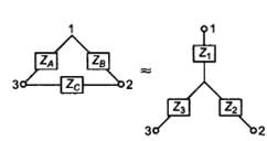
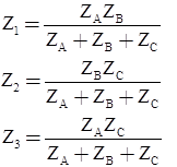
Note: Both Star Delta Transformation and Delta Star Transformation allows us to convert one type of circuit connection into another type in order for us to easily analyse the circuit. These transformation techniques can be used to good effect for either star or delta circuits containing resistances or impedances.
Three Phase Power:
If line values of voltage and current are known, the power (watts) of a pure resistive load is:

If the phase values of voltage and current are known, the apparent power is:
|
73 videos|139 docs|62 tests
|
FAQs on Study Notes For Three Phase AC Circuit - Network Theory (Electric Circuits) - Electrical Engineering (EE)
| 1. What is a three-phase AC circuit? |  |
| 2. How does a three-phase AC circuit work? |  |
| 3. What are the advantages of a three-phase AC circuit? |  |
| 4. How do you calculate power in a three-phase AC circuit? |  |
| 5. What is the significance of the 120-degree phase shift in a three-phase AC circuit? |  |


