JEE Advanced (Subjective Type Questions): Current Electricity | Chapter-wise Tests for JEE Main & Advanced PDF Download
Q.1. A heater is designed to operate with a power of 1000 watts in a 100 volt line. It is connected in a combinations with a resistance of 10 ohms and a resistance R to a 100 volts mains as shown in the figure. What should be the value of R so that the heater operates with a power of 62.5 watts.

Ans. 5Ω
Solutions. The resistance of the heater is

The power on which it operates is 62.5 W

Since the voltage drop across the heater is 25V hence voltage drop across 10Ω resistor is (100 – 25) = 75V.

This current divides into two parts. Let I1 be the current that passes through the heater. Therefore
25 = I1 × 10
I1 = 2.5 A
Thus current through R is 5A.

Applying Ohm's law across R, we get 25 = 5 × R
⇒ R = 5Ω
Q.2. If a copper wire is stretched to make it 0.1% longer what is the percentage change in its resistance?
Ans. 0.2%
Solutions.
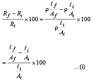
Let the initial length of the wire be 100 cm, then the new

Let Ai and Af be the initial and final area of cross-section.
Then
100 ×Ai = 100.1 Af

From (i), (ii) and (iii)


Thus the resistance increases by 0.2%.
Alternatively for small change 
Q.3. All resistances in the diagram below are in ohms. Find the effective resistance between the points A and B.
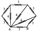
Ans. 2Ω
Solution.
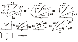
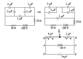
Q.4. In the diagram shown find the potential difference between the points A and B and between the points B and C in the steady state.
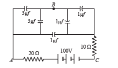
Ans. VAB = 25 V, VBC = 75 V
Solution. Applying Kirchoff's law in loop AQBRC

∴ Potential difference between AB = 150/6=25V
∴ Potential difference between BC = 100 – 25 = 75V
Q.5. A battery of emf 2 volts and internal resistance 0.1 ohm is being charged with a current of 5 amps. In what direction will the current flow inside the battery?What is the potential difference between the two terminal of the battery?
Ans. Positive to negative terminal, 2.5 V
Solution. NOTE : The current will flow from the positive terminal to the negative terminal inside the battery.
During charging the potential difference V = E + Ir = 2 + 5 × 0.1 = 2.5 V
Q.6.State ohm’s law.
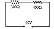
In the circuit shown in figure, a voltmeter reads 30 volts when it is connected across 400 ohm resistance. Calculate what the same voltmeter will read when it is connected across the 300 ohm resistance.
Ans.22.5 V
Solution. Potential difference across the 400 Ω resistance = 30 V.
Therefore, potential difference across the 300 Ω resistance = 60 – 30V = 30 V. Let R be the resistance of the voltmeter.
As the voltmeter is in the parallel with the 400Ω resistance, their combined resistance is

As the potential difference of 60 V is equally shared between the 300 Ω and 400 Ω resistance. R' should be equal to 300 Ω.
Thus

which gives R = 1200Ω, is the resistance of the voltmeter.
When the voltmeter is connected across the 300Ω resistance, their combined resistance is

∴ Total resistance in the ciruit = 400 + 240 = 640 Ω
∴ Current in the circuit is

∴ Voltmeter reading = Potential difference across 240 Ω resistance

Q.7.In the circuit shown in fig E1 =3 volts, E2 = 2 volts, E3 = 1 volt and R = r1 = r2 = r3 = 1 ohm.
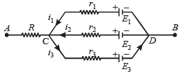
(i) Find the potential difference between the points A and B and the currents through each branch.
(ii) If r2 is short circuited and the point A is connected to point B, find the currents through E1, E2 E3 and the resistor R
Ans.(i) 2V, 1A, 0A, 1A (ii) 1A, 2A, 1A; 2A
Solution.

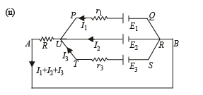
Applying Kirchoff's law in PQRUP starting from P moving clockwise

Applying Kirchoff's law in URSTU starting from U moving clockwise

NOTE : The – ve sign of I3 indicates that the direction of current in branch UTSR is opposite to that assumed.
Applying Kirchoff's law in AURBA starting from A moving clockwise.

Current through R is I1 + I2 + I3 = 2A
Q.8. Calculate the steady state current in the 2-ohm resistor shown in the circuit in the figure. The internal resistance of the battery is negligible and the capacitance of the condenser C is 0.2 microfarad.
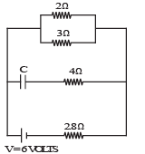
Ans. 0.9A
Solution. 
Total current through the battery

Q.9. In the circuit shown in figure E, F, G, H are cells of emf 2, 1, 3 and 1 volt respectively, and their internal resistances are 2, 1, 3 and 1 ohm respectively.
Calculate : (i) the potential difference between B and D and
(ii) the potential difference across the terminals of each cells G and H
Ans.
Solution. Let I2 current flow through the branch DCB
∴ By Kirchoff's junction law, current in branch DB will be I2 – I1 as shown in the figure.
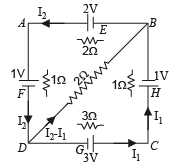
Applying Kirchoff's law in loop BDAB

Applying Kirchoff's law in loop BCDB, we get

Solving (i) and (ii), we get I1 = 6/13 amp
and I2 = 5/13amp
(i) To find the p.d. between B and D, we move from B to D

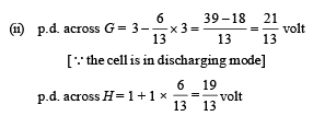
[∴cell is in charging mode]
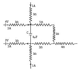
Q.10.A part of ciucuit in a steady state along with the currents flowing in the branches, the values of resistances etc., is shown in the figure. Calculate the energy stored in the capacitor C (4µF)
Ans. 8 × 10⁻⁴ J
Solution. Applying Kirchoff's first law at junction M, we get the current i1 = 3A
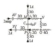
Applying Kirchoff's first law at junction P, we get current i2 = 1A
NOTE : No current flows through capacitor at steady state.
Moving the loop along MNO to P

Energy stored in the capacitor

Q.11. An infinite ladder network of resistances is constructed with a1 ohm and 2 ohm resistances, as shown in fig.
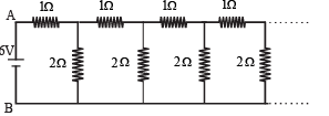
The 6 volt battery between A and B has negligible internal resistance : (i) Show that the effective resistance between A and B is 2 ohms. (ii) What is the current that passes through the 2 ohm resistance nearest to the battery ?
Ans.(ii) 1.5A
Solution. (i) Let the effective resistance between points C and D be R then the circuit can be redrawn as shown The effective resistance between A and B is
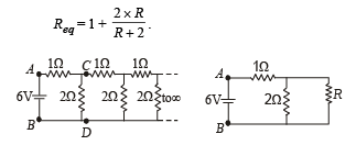
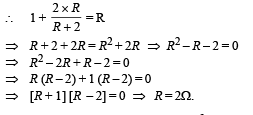
This resistance Req can be taken as R because if we add one identical item to infinite items then the result will almost be the same.

Q.12.In the given circuit
E1 = 3E2=2E3 = 6 volts R1 = 2R4 = 6 ohms R3 = 2R2 = 4 ohms C = 5 μ f .
Find the current in R3 and the energy stored in the capacitor.
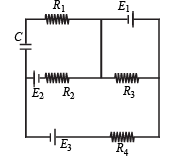
Ans. 1.5 A, 1.44 × 10⁻⁵ J
Solution.
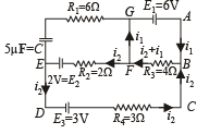
Applying Kirchoff's law in ABFGA 6 – (i1 + i2) 4 = 0 ... (i)
Applying Kirchoff's law in BCDEFB i2 × 3 – 3 – 2 + 2i2 + (i2 + i1) 4 = 0 ... (ii)
Putting the value of 4 (i1 + i2) = 6 in (ii)
3i2 – 5 + 2i2 + 6 = 0

Substituting this value in (i), we get

Therefore current in R3
= i1 + i2 = 1.7 – 0.2 = 1.5 A
To find the p.d. across the capacitor
VE – 2 – 0.2 × 2 = VG
∴ VE – VG = 2.4 V
or V = 24 V
∴ Energy stored in capacitor = 1/2 CV2
=1/2× 5 × 10–6 × (2.4)2 = 1.44 × 10⁻⁵ J
Q.13. An electrical circuit is shown in Fig. Calculate the potential difference across the resistor of 400 ohm, as will be measured by the voltmeter V of resistance 400 ohm, either by applying Kirchhoff’s rules or otherwise.
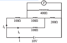
Ans.6.67 V
Solution.We can redraw the circuit as.
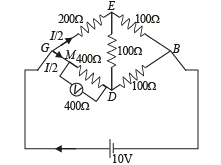
The equivalent resistance between G and D is

∴ It is a case of balanced wheatstone bridge.
The equivalent resistance across G and B is

NOTE : Since RGEB = RGDB the current is divided at G into two equal parts  The current I/2 further divides into two equal parts at M.Therefore the potential difference across the voltmeter

Q.14.In the circuit shown in Figure, the battery is an ideal one, with emf V. The capacitor is initially uncharged. The switch S is closed at time t = 0.
(a) Find the charge Q on the capacitor at time t. (b) Find the current in AB at time t. What is its limiting value as t →∞ :
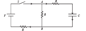
Ans.
Solution. Let at any time t charge on capacitor C be Q. Let currents are as shown in fig. Since charge Q will increase with time 't' therefore i1 = dQ/dt
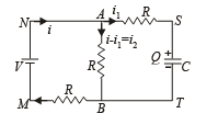
(a) Applying Kirchoff's second law in the loop MNABM
V = (i – i1) R + iR or V = 2iR – i1R ... (i)
Similarly, applying Kirchoff's second law in loop MNSTM, we have

Eliminating i from equation (1) and (2), we get
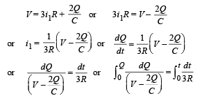

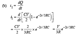
From equation (i)

∴ Current through AB


Q.15. A thin uniform wire AB of length 1m, an unknown resistance X and a resistance of 12 Ω are connected by thick conducting strips, as shown in the figure. A battery and a galvanometer (with a sliding jockey connected to it) are also available. Connections are to be made to measure the unknown resistance X using the principle of Wheatstone bridge. Answer the following questions.

(a) Are there positive and negative terminals on the galvanometer? (b) Copy the figure in your answer book and show the battery and the galvanometer (with jockey) connected at appropriate points.
Ans. (a) No (b) 8Ω
Solution.(a) No. There are no positive and negative terminals on the galvanometer.
NOTE : Whenever there is no current, the pointer of the galvanometer is at zero. The pointer swings on both side of zero depending on the direction of current.

where r is the resistance per unit length.

Q.16. How a battery is to be connected so that the shown rheostat will behave like a potential divider? Also indicate the points about which output can be taken.

Ans. Battery connected across A and B. Output across A and C or B and C.
Solution. Battery should be connected across A and B. Output can be taken across the terminals A and C or B and C.

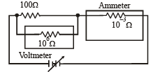
Q.17. Draw the circuit diagram to verify Ohm’s Law with the help of a main resistance of 100 W and two galvanometers of resistances 106 W and 10–3 W an d a source of varying emf.Show the correct positions of voltmeter and ammeter.
Solution. For the experimental verification of Ohm's law, ammeter and voltmeter should be connected as shown in the figure.
A voltmeter is a high resistance galvanometer (106Ω) which is connected in parallel with the main resistance of 100Ω.
An ammeter is a low resistance galvanometer (10–3Ω) which is connected in parallel with the main resistance.
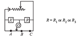
Q.18. An unknown resistance X is to be deter m in ed using resistances R1, R2 or R3. Their corresponding null points are A, B and C. Find which of the above will give the most accurate reading and why?
Ans. R2
Solution. KEY CONEPT : At all null points the wheatstone bridge will be balanced
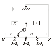

where R is a constant r1 and r2 are variable.
The maximum fractional error is


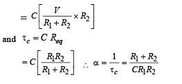
Q.19. In the given circuit, the switch S is closed at time t = 0. The charge Q on the capacitor at any instant t is given by Q(t) = Q(1 – e–αt). Find the value of Q0 and α in terms of given parameters as shown in the circuit.
Ans.
Solution. Given Q = Q0[1 – e–αt] Here Q0 = Maximum charge and

Now the maximum charge Q0 = C [V0 ] where V0 = max potential difference across C
|
446 docs|929 tests
|


