Superposition Theorem for AC Circuits | Network Theory (Electric Circuits) - Electrical Engineering (EE) PDF Download
- The theorem becomes important if the circuit has sources operating at different frequencies.
- In this case, since the impedances depend on frequency, we must have a different frequency domain circuit for each frequency.
- The total response must be obtained by adding the individual responses in the time domain.
- It is incorrect to try to add the responses in the phasor or frequency domain.
- It is because the exponential factor ejωt is implicit in sinusoidal analysis, and that factor would change for every angular frequency ω.
- It would therefore not make sense to add responses at different frequencies in the phasor domain.
- Hence, when a circuit has sources operating at different frequencies, one must add the responses due to the individual frequencies in the time domain.
Superposition Theorem for AC Circuits Examples
For better understanding, let us review the examples below:
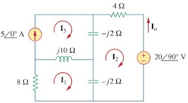
1. Use the superposition theorem to find Io in the circuit in Figure.
Let
..... (1.1)
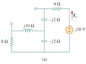
where I‘o and I“o are due to the voltage and current sources, respectively. To find I‘o, consider the circuit in Figure.(2a).
If we let Z be the parallel combination of –j2 and 8 + j10, then
and current Io is
or
........ (1.2)
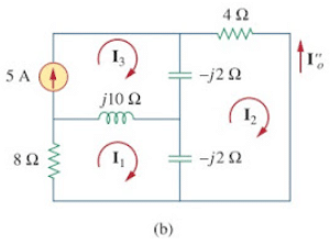
To get I“o, consider the circuit in Figure.(2b). For mesh 1,....... (1.3)
For mesh 2,.......(1.4)
For mesh 3,.......(1.5)
From Equations.(1.4) and (1.5),
Expressing I1 in terms of I2 gives..... (1.6)
Substituting Equations.(1.5) and (1.6) into Equation.(1.3), we get
or
Current I“o is obtained as..........(1.7)
From Equations.(1.2) and (1.7), we write
2. Find vo in the circuit of Figure. using the superposition theorem.

Since the circuit operates at three different frequencies (ω = 0 for the dc voltage source), one way to obtain a solution is to use superposition, which breaks the problem into single-frequency problems. So we let
....... (2.1)
where v1 is due to the 5 V dc voltage source, v2 is due to the 10 cos 2t V voltage source, and v3 is due to the 2 sin 5t A current source.
To find v1, we set to zero all sources except the 5 V dc source.
We recall that at steady state, a capacitor is an open circuit to dc while an inductor is a short circuit to dc.
There is an alternative way of looking at this. Since ω = 0, jωL = 0, 1/jωC = ∞.
Either way, the equivalent circuit is as shown in Figure. By voltage division,..... (2.2)
To find v2, we set to zero both the 5 V source and the 2 sin 5t current source and transform the circuit to the frequency domain.The equivalent circuit is now as shown in Figure. Let
Figure. The solution of Figure.: (a) setting all sources to zero except the 5 V dc source, (b) setting all sources to zero except the ac voltage source, (c) setting all sources to zero except the ac current source.
By voltage division,
In the time domain,..... (2.3)
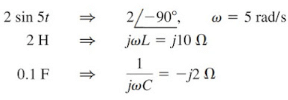
To obtain v3, we set the voltage sources to zero and transform what is left to the frequency domain.
The equivalent circuit is in Figure. Let
By current division,
In the time domain,.... (2.4)
Substituting Equations.(2.2) to (2.4) into Equation.(2.1), we have
|
73 videos|139 docs|62 tests
|
FAQs on Superposition Theorem for AC Circuits - Network Theory (Electric Circuits) - Electrical Engineering (EE)
| 1. What is the Superposition Theorem for AC circuits? |  |
| 2. How does the Superposition Theorem work in AC circuits? |  |
| 3. Can the Superposition Theorem be used for non-linear AC circuits? |  |
| 4. What are the limitations of the Superposition Theorem in AC circuits? |  |
| 5. Are there any practical applications of the Superposition Theorem in AC circuits? |  |


