Transmission Lines - Electrical Engineering (EE) PDF Download

Transmission Lines
Measurement and/or control signals are carried through various transmission lines. Various process piping, connection and transmission lines, as per the standard set by International Society of Automation (ISA), are listed in the following figure.
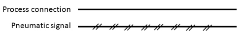
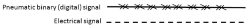
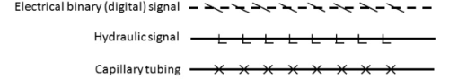
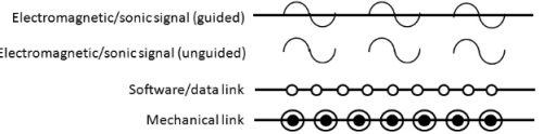
Fig. IV.4: Representation of process piping, connection and transmission lines
A heavy solid line represents piping,a thin solid line represents process connections to instruments, a dashed line represents electrical signals (e.g., 4–20 mA connections), a slashed line represents pneumatic signal tubes, a line with circles on it represents data links. Other connection symbols include capillary tubing for filled systems, (e.g., remote diaphragm seals), hydraulic signal lines, and guided/unguided electromagnetic or sonic signals. Electric/electromagnetic signals are instantaneous. Unless the process changes very fast and/or the transmission lines are too long, the dynamic behaviors of electric/electromagnetic transmissions are also usually ignored.
Final Control Element
The hardware component of a control loop that resides between the process and the controller and implements the control action is called the Final Control Element (FCE). It receives the control signal from the controller and regulates the value of the manipulated variable accordingly. An ideal FCE should be an instantaneously operating hardware that does not induce any time lag between process and controller. However, in reality it is impossible to find such an instantaneously operating FCE. Nevertheless any FCE, whose time constant is very small, is considered to be a good hardware for a control system.
Various types of FCEs are available in process industries that are widely used in control applications. They can be largely classified based on their energy source, viz . Pneumatic, Hydraulic and Electric, etc .
A few of them are discussed in Module VII.
Dynamic behaviour of feedback controller
Consider the generalized closed loop process given in the Fig IV.5.
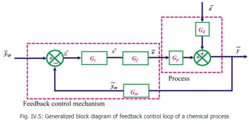
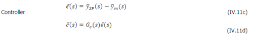
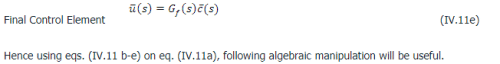
If we assume that the transmission line does not affect the signal flow, dynamics of the transmission lines can be completely ignored. Hence the following sub-processes will constitute the overall dynamics of the process: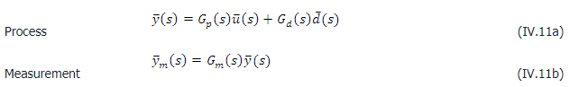
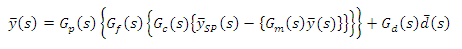 12
12
Rearranging the above we obtain,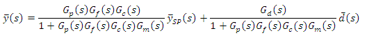 13
13
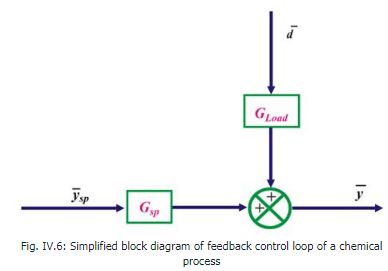
The eq. (13) represents the closed loop response of the process. The pictorial representation is given in the Fig IV.6
 14
14
 15
15
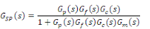
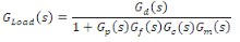
Gsp and Gload are the closed loop transfer functions (CLTF) of the process.Gsp maps the effect of change of setpoint on the process output whereas Gload maps the effect of change of load (disturbance) on the process output.
Two types of control problems are encountered with the feedback control systems, viz . servo and regulatory.
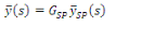
When setpoint of a process undergoes a change while the disturbance affecting the process remains constant, i.e.  , the objective of the control system would be to steer the output as close as the setpoint trajectory. In such situation,
 16
16
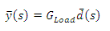
However, when the setpoint remains constant, i.e.  , while the disturbance forces the process output to move out of the track of the setpoint, the objective of the control system would be to reject the effect of disturbance as soon as possible and steer the output back to the setpoint trajectory. In such situation,
 17
17
Note that the CLTFs depend not only on the process transfer functions, but also on the transfer functions of measuring element, controller and final control element.
To expedite the construction of overall closed loop transfer function of any feedback loop, following rules may be applied:
1. The denominator of the overall transfer function is “the product of all transfer functions in the feedback loop PLUS one” i.e ., 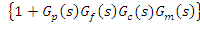
2. The numerator of the overall transfer function is “the product of all transfer functions in the forward path between setpoint and the controlled output (for servo problem) or the load and the controlled output (for regulatory problem)” i.e ., 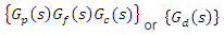
FAQs on Transmission Lines - Electrical Engineering (EE)
| 1. What are transmission lines and how do they work? |  |
| 2. What are the different types of transmission lines? | |
| 3. How do transmission lines affect signal quality? | |
| 4. What is the importance of impedance matching in transmission lines? | |
| 5. How do transmission lines handle high-frequency signals? | |


Transmission Lines - Electrical Engineering (EE)
,Extra Questions
,mock tests for examination
,Important questions
,video lectures
,past year papers
,practice quizzes
,Sample Paper
,study material
,Previous Year Questions with Solutions
,Objective type Questions
,Free
,MCQs
,shortcuts and tricks
,Transmission Lines - Electrical Engineering (EE)
,Viva Questions
,Exam
,ppt
,Semester Notes
,Summary
,Transmission Lines - Electrical Engineering (EE)
;


Transmission Lines Free PDF Download
Importance of Transmission Lines
Transmission Lines Notes
Transmission Lines Electrical Engineering (EE) Questions
Study Transmission Lines on the App
|
© EduRev
|
Education Revolution
|


|


within 7 days!