Turbomachinery- Notes | Fluid Mechanics for Mechanical Engineering PDF Download
Introduction
Turbomachine is defined as a device in which energy transfer takes place between a flowing fluid and a rotating element resulting in a change of pressure and momentum of the fluid. Energy is transferred into or out of the turbomachine mechanically using input/output shafts.
Principal Parts of a Turbo Machine- Rotating element consisting of a rotor on which are mounted blades.
- A stationary element in the form of guide blades, nozzles, etc.
- Input/output shafts.
- Housing
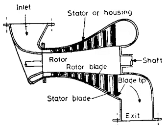
A schematic cross-sectional view of a steam turbine showing the principal parts of a turbomachine.
Functions
- The rotor functions to absorb/deliver energy to the flowing fluid.
- The stator is a stationary element that may be of many types:-
(i) Guide blades that function to direct the flowing fluid in such a way that energy transfer is maximized.
(ii) Nozzles which function to convert pressure energy of the fluid to kinetic energy
(iii) Diffusers which function to convert kinetic energy to pressure energy of the fluid. - The input /output shafts function to deliver/receive mechanical energy to or from the machine.
- The housing is a protective enclosure that also functions to provide a path of flowing fluid. While a rotor & input /output shaft are essential parts of all turbomachines, the stator & the housing are optional.
Classification of Turbo Machines
- According to the nature of energy transfer:
(i) Power generating turbomachines: In this, energy is transferred from the flowing fluid to the rotor. Hence, the enthalpy of the flowing fluid decreases as it flows across. There is a need for an output shaft.
(ii) Example: Hydraulic turbines such as Francis turbine, Pelton wheel turbine, Kaplan turbine, steam turbine such as De-Laval turbine, Parsons Turbine etc, Gas turbines etc,
(iii) Power absorbing Turbomachines: In this, energy is transferred from the rotor to the flowing fluid. The enthalpy of the fluid increases as it flows there is a need for an input shaft.
(iv) Example: Centrifugal pump, Compressor, blower, fan etc,
(v) Power transmitting turbomachines: In this energy is transferred from one rotor to another by means of a flowing fluid. There is a need for input/output shafts. The transfer of energy occurs due to fluid action.
(vi) Example: Hydraulic coupling, torque converter etc.
Schematic representation of different types of turbomachine based on fluid flow
- Axial flow fan.
- Radial outward flows fan.
- Mixed flow hydraulic turbine.
- Based on the type of fluid flow:
(i) Tangential flow in which fluid flows tangentially to the rotor
Example: Pelton wheel etc,
(ii) Axial flow in which the fluid flows more or less parallel to the axes of the shafts /rotors.
Example: Kaplan turbine, Axial flow compressor.
(iii) Radial flow in which fluid flows along the radius of the rotor this is again classified as:
(a) Radially inward flow.
Example: Old fancies turbine.
(b) Radially outward flow.
Example: Centrifugal Pump.
(iv) Mixed flow which involves radius entry & axial exit or vice-versa.
Example: Modern francises turbine & Centrifugal Pump. - Based on the type of Head
(i) High head &low discharge.
Example: Pelton wheel.
(ii) Medium head &medium discharge.
Example: Francis turbine.
(iii) Low head & high discharge.
Example: Kaplan turbine.
Application of 1st & 2nd law of thermodynamics of turbomachines
In a turbomachine, the fluctuations in the properties when observed over a period of time are found to be negligible. Hence, a turbomachine may be treated as a steady flow machine with reasonable accuracy & hence, we may apply the steady flow energy equation for the analysis of turbomachine.
Hence we may write

Where subscript ‘1’ is at the point of entry & subscript ‘2’ is at the point of exit.
It is also true that thermal losses are minimal compared to the amount of work transferred & hence may be neglected. Hence we may write,

Where, h02 & h01 are stagnation exit & entry respectively.
w = ∆h0.
In a power generating turbomachine, ∆h0 is negative (since h02 < h01) & hence w is positive.
On the same line, for a power absorbing turbomachine, ∆h0 is positive (since h02 > h01) & hence w is negative.
From the 2nd law of Thermodynamics:
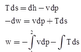
In the above relation, we note that vdp would be a negative quantity for a power generating turbo machine & positive for power absorbing turbomachine.
Hence Tds which is always a positive quantity would reduce the amount of work generated in the former case & increase the work absorbed in the latter case.
Efficiency of a turbomachine
Generally, we define 2 types of turbomachine .in case of turbomachine to account for various losses 2 types of efficiency is considered:
- Hydraulic efficiency/isentropic efficiency
- Mechanical efficiency.
- Hydraulic efficiency/isentropic efficiency
To account for the energy loss between the fluid & the rotor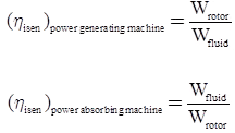
- Mechanical efficiency
To account for the energy loss between the rotor & the shaft.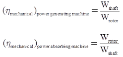
Schematic representation of Compression & Expansion process
- Power absorbing machine.
- Power generating machine.
- Power generating machine
Wact = h01 - h02
Wisen = Wt - t = h01 - h102
Wt - s = h01 - h102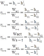
- Power absorbing turbomachine
Wact = h02 - h01
Wisen = Wt - t = h102 - h01
Wt - s = h102 - h01
Ws - t = h12 - h01
Ws - s = h12 - h1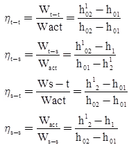
Analysis of energy transfer in turbomachines requires a consideration of the kinematics and dynamic factors involved. The factors include changes in the fluid velocity, rotor velocity and the forces caused due to change in the velocity.
We apply Newton’s second law of motion as applicable to a rotary movement. i.e., Torque is proportional to the rate of change of angular momentum.
T = d(mVr)/dt
Another important consideration is the treatment of turbomachine as a steady flow machine.
- This involves the following assumptions:
- The Mass-flow rate is constant.
- State of fluid at any given point does not change.
- Heat and Work transfer are constant.
- Leakage losses are negligible.
- Same steady mass of fluid flows through all section.
Velocity Components
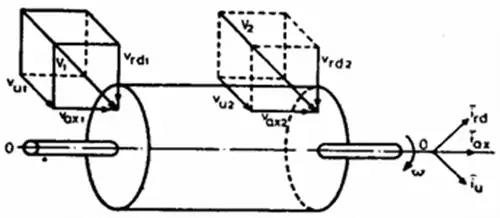 Velocity components through a rotor
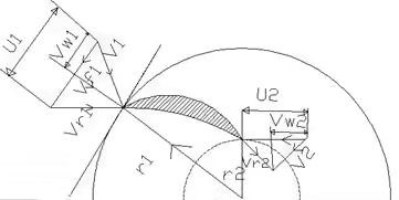
The fluid enters the rotor with an absolute velocity say V1 and leaves with an absolute velocity say V2.
The absolute velocity of the fluid will have components in the axial, radial and tangential direction which may be referred to as Va,Vw and Vf respectively.
The axial components do not participate in the energy transfer but cause a thrust which is borne by the thrust bearings. The radial components also do not participate in the energy transfer but cause a thrust which is borne by the journal bearings. The only components which participate in the energy transfer is the tangential component Vw.
Va1 and Va2: Axial components of V1 and V2 respectively.
Vf1 and Vf2: Radial components of V1 and V2 respectively.
Vw1 and Vw2: Tangential components of V1 and V2 respectively referred to as whirl
velocity, flow velocity. Let the rotor move with an angular velocity ω.
|
56 videos|154 docs|75 tests
|
FAQs on Turbomachinery- Notes - Fluid Mechanics for Mechanical Engineering
| 1. What is turbomachinery? |  |
| 2. What are the types of turbomachinery? |  |
| 3. How does turbomachinery work? |  |
| 4. What are the main components of turbomachinery? |  |
| 5. What are the applications of turbomachinery? |  |


