Wall Shear Stress - 1 | Fluid Mechanics for Mechanical Engineering PDF Download

Wall Shear Stress
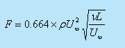
- With the profile known, wall shear can be evaluated as
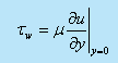
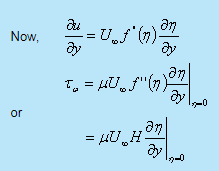
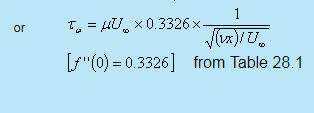
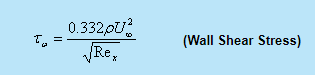 (29.1a)
and the local skin friction coefficient is 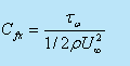
Substituting from (29.1a) we get
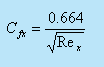 (Skin Friction Coefficient) (29.1B)
- In 1951, Liepmann and Dhawan , measured the shearing stress on a flat plate directly. Their results showed a striking confirmation of Eq. (29.1).
- Total frictional force per unit width for the plate of length L is
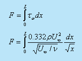
or
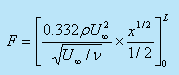
or
and the average skin friction coefficient is
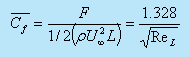 (29.3)
where, Re = U∞ L/v
For a flat plate of length L in the streamwise direction and width w perpendicular to the flow, the Drag D would be
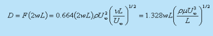 (29.4)
Boundary Layer Thickness
- Since
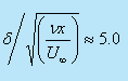
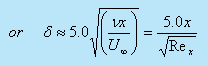
 , it is customary to select the boundary layer thickness δ as that point where
  approaches 0.99.
 - From Table 28.1, reaches 0.99 at η= 5.0 and we can write
- However, the aforesaid definition of boundary layer thickness is somewhat arbitrary, a physically more meaningful measure of boundary layer estimation is expressed through displacement thickness .
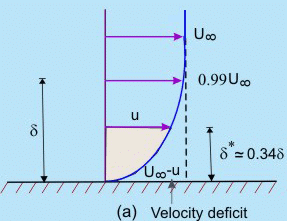
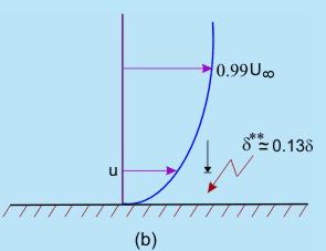
Fig. 29.1 (Displacement thickness) (b) Momentum thickness
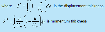
Displacement thickness (δ*) : It is defined as the distance by which the external potential flow is displaced outwards due to the decrease in velocity in the boundary layer.
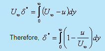 (29.6)
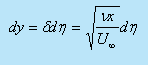
- Substituting the values of u / U∞ and n from Eqs (28.21a) and (28.19) into Eq.(29.6), we obtain
 (29.7)
Following the analogy of the displacement thickness, a momentum thickness may be defined.
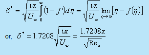
Momentum thickness ( δ** ): It is defined as the loss of momentum in the boundary layer as compared with that of potential flow. Thus
 (29.8)
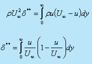
With the substitution of u / U∞ and n from Eg. (28.21a) and (28.19), we can evaluate numerically the value of δ** for a flat plate as
 (29.9)
The relationships between δδ*and δ**have been shown in Fig. 29.1.
Momentum-Integral Equations For The Boundary Layer
- To employ boundary layer concepts in real engineering designs, we need approximate methods that would quickly lead to an answer even if the accuracy is somewhat less.
- Karman and Pohlhausen devised a simplified method by satisfying only the boundary conditions of the boundary layer flow rather than satisfying Prandtl's differential equations for each and every particle within the boundary layer. We shall discuss this method herein.
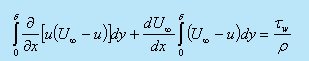
Consider the case of steady, two-dimensional and incompressible flow, i.e. we shall refer to Eqs (28.10) to (28.14). Upon integrating the dimensional form of Eq. (28.10) with respect to y = 0 (wall) to y = δ (where δ signifies the interface of the free stream and the boundary layer), we obtain
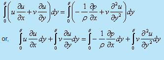 (29.10)
- The second term of the left hand side can be expanded as
 (29.11)
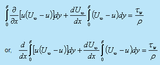
- Substituting Eq. (29.11) in Eq. (29.10) we obtain
 (29.12)
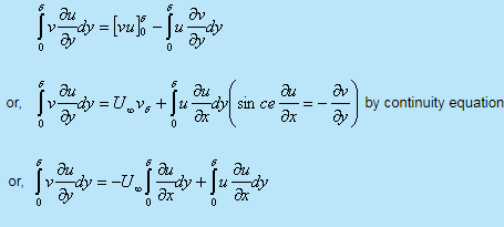
- Substituting the relation between
 and the free stream velocity U∞ for the inviscid zone in Eq. (29.12) we get
which is reduced to
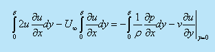
- Since the integrals vanish outside the boundary layer, we are allowed to increase the integration limit to infinity (i.e δ = ∞. )
 (29.13)
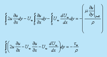
Substituting Eq. (29.6) and (29.7) in Eq. (29.13) we obtain
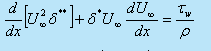 (29.14)
Equation (29.14) is known as momentum integral equation for two dimensional incompressible laminar boundary layer. The same remains valid for turbulent boundary layers as well.
Needless to say, the wall shear stress (tw) will be different for laminar and turbulent flows.
- The term
 signifies space-wise acceleration of the free stream. Existence of this term means that free stream pressure gradient is present in the flow direction.
 - For example, we get finite value of outside the boundary layer in the entrance region of a pipe or a channel. For external flows, the existence of depends on the shape of the body.
- During the flow over a flat plate, = 0 and the momentum integral equation is reduced to
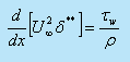 (29.15)
Seperation of Boundary Layer
- It has been observed that the flow is reversed at the vicinity of the wall under certain conditions.
- The phenomenon is termed as separation of boundary layer.
- Separation takes place due to excessive momentum loss near the wall in a boundary layer trying to move downstream against increasing pressure, i.e.,
 , which is called adverse pressure gradient.
 - Figure 29.2 shows the flow past a circular cylinder, in an infinite medium
- Up to θ = 900, the flow area is like a constricted passage and the flow behaviour is like that of a nozzle.
- Beyond θ = 900 the flow area is diverged, therefore, the flow behaviour is much similar to a diffuser
This dictates the inviscid pressure distribution on the cylinder which is shown by a firm line in Fig. 29.2.
Here
Pw : pressure in the free stream
U∞ : velocity in the free stream and
P : is the local pressure on the cylinder.
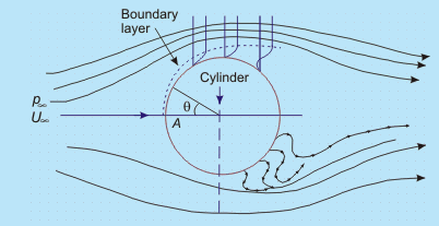
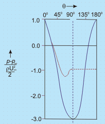
Fig. 29.2 Flow separation and formation of wake behind a circular cylinder
- Until θ = 900 the pressure force and the force due to streamwise acceleration i.e. inertia forces are acting in the same direction (pressure gradient beingnegative/favourable)
- Beyond θ = 900 , the pressure gradient is positive or adverse. Due to the adverse pressure gradient the pressure force and the force due to acceleration will be opposing each other in the in viscid zone of this part.
So long as no viscous effect is considered, the situation does not cause any sensation.
In the viscid region (near the solid boundary),
- Up to θ = 900 , the viscous force opposes the combined pressure force and the force due to acceleration. Fluid particles overcome this viscous resistance
due to continuous conversion of pressure force into kinetic energy. - Beyond θ = 900 , within the viscous zone, the flow structure becomes different. It is seen that the force due to acceleration is opposed by both the viscous force and pressure force.
- Depending upon the magnitude of adverse pressure gradient, somewhere around θ = 900 , the fluid particles, in the boundary layer are separated from the wall and driven in the upstream direction. However, the far field external stream pushes back these separated layers together with it and develops a broad pulsating wake behind the cylinder.
- The mathematical explanation of flow-separation : The point of separation may be defined as the limit between forward and reverse flow in the layer very close to the wall, i.e., at the point of separation
 ( 29.16)
This means that the shear stress at the wall, tw = 0 . But at this point, the adverse pressure continues to exist and at the downstream of this point the flow acts in a reverse direction resulting in a back flow.
- We can also explain flow separation using the argument about the second derivative of velocity u at the wall. From the dimensional form of the momentum at the wall, where u = v = 0, we can write
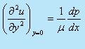 ( 29.17)
- Consider the situation due to a favourable pressure gradient where
 we have,
 -
 . (From Eq. (29.17))
 - As we proceed towards the free stream, the velocity u approaches U∞ asymptotically, so
 decreases at a continuously lesser rate in y direction.
 - This means that
 remains less than zero near the edge of the boundary layer.
 - The curvature of a velocity profile is always negative as shown in (Fig. 29.3a)
-
- Consider the case of adverse pressure gradient,

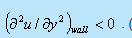
- At the boundary, the curvature of the profile must be positive (since ).
- Near the interface of boundary layer and free stream the previous argument regarding and still holds good and the curvature is negative.
- Thus we observe that for an adverse pressure gradient, there must exist a point for which = 0 . This point is known as point of inflection of the velocity profile in the boundary layer as shown in Fig. 29.3b
- However, point of separation means = 0 at the wall.
- at the wall since separation can only occur due to adverse pressure gradient. But we have already seen that at the edge of the boundary layer,
 . It is therefore, clear that if there is a point of separation, there must exist a point of inflection in the velocity profile.
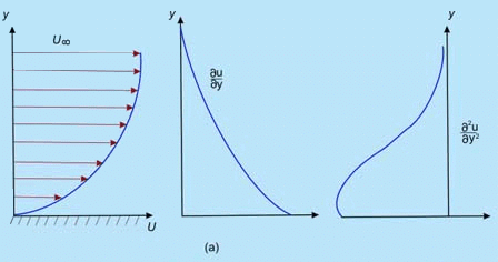
- At the boundary, the curvature of the profile must be positive (since
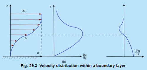
(a) Favourable pressure gradient,
(b) adverse pressure gradient, 
- Let us reconsider the flow past a circular cylinder and continue our discussion on the wake behind a cylinder. The pressure distribution which was shown by the firm line in Fig. 21.5 is obtained from the potential flow theory. However. somewhere near θ = 900 (in experiments it has been observed to be at θ = 810) . the boundary layer detaches itself from the wall.
- Meanwhile, pressure in the wake remains close to separation-point-pressure since the eddies (formed as a consequence of the retarded layers being carried together with the upper layer through the action of shear) cannot convert rotational kinetic energy into pressure head. The actual pressure distribution is shown by the dotted line in Fig. 29.3.
- Since the wake zone pressure is less than that of the forward stagnation point (pressure at point A in Fig. 29.3), the cylinder experiences a drag force which is basically attributed to the pressure difference.
The drag force, brought about by the pressure difference is known as form drag whereas the shear stress at the wall gives rise to skin friction drag. Generally, these two drag forces together are responsible for resultant drag on a body
|
56 videos|146 docs|75 tests
|
FAQs on Wall Shear Stress - 1 - Fluid Mechanics for Mechanical Engineering
| 1. What is wall shear stress in civil engineering? |  |
| 2. How is wall shear stress calculated in civil engineering? | |
| 3. What factors affect the magnitude of wall shear stress in civil engineering? | |
| 4. Why is wall shear stress important in civil engineering? | |
| 5. How can wall shear stress be controlled or mitigated in civil engineering projects? | |


Viva Questions
,Semester Notes
,Exam
,Previous Year Questions with Solutions
,ppt
,Wall Shear Stress - 1 | Fluid Mechanics for Mechanical Engineering
,MCQs
,Objective type Questions
,Wall Shear Stress - 1 | Fluid Mechanics for Mechanical Engineering
,video lectures
,study material
,shortcuts and tricks
,practice quizzes
,Free
,Wall Shear Stress - 1 | Fluid Mechanics for Mechanical Engineering
,mock tests for examination
,Sample Paper
,past year papers
,Extra Questions
,Summary
,Important questions
;


Wall Shear Stress - 1 Free PDF Download
Importance of Wall Shear Stress - 1
Wall Shear Stress - 1 Notes
Wall Shear Stress - 1 Mechanical Engineering Questions
Study Wall Shear Stress - 1 on the App
|
© EduRev
|
Education Revolution
|


|


