Thyristor | Power Electronics - Electrical Engineering (EE) PDF Download
| Table of contents |

|
| Thyristor |

|
| SCR |

|
| VI characteristics of SCR |

|
| Two Transistor Analogy of A Thyristor |

|
| Thyristor Turn-on-Methods |

|
| SCR Protection |

|
| Thyristor Firing Circuits |

|
Thyristor
- Thyristors are a family of devices, construction-wise similar to the transistor but function as Thyratron tubes.
- The most important and most widely used member of the thyristor family is the SCR (silicon-controlled rectifier)
SCR
Silicon Controlled Rectifier is a four-layer, three-junction device, having three terminals namely anode (A), cathode (K), and gate (G) as shown in the figure below:
 SCR
SCR
VI characteristics of SCR
The VI characteristic of SCR can be classified into three modes.
1. Reverse blocking mode
2. Forward blocking mode
3. Forward conducting mode

 V-I Characteristics of SCR
where,
VBO = Forward break over voltage
VBR = Reverse break over voltage
Ig = Gate current
Reverse Blocking Mode
In the elementary circuit diagram, if A is made negative w.r.t. K i.e. Va = –ve, junction J1 and J3 are reverse biased while J2 is forward biased.

- SCR appears like three diodes are connected as shown in Figure (b). As J1 and J2 are R.B., they offer high resistance Rr (ideally open-circuited), while J2 being F.B. offers very low resistance Rf (ideally short-circuited.)


- A very small leakage current flow (like reverse leakage current of diode) in the circuit.
- As reverse voltage Va (–ve) is increased further at a particular value of voltage say VBR (–ve) reverse biased junction J1 and J3 breakdown hence current rises sharply, (the characteristic represented in the third quadrant with load resistance to zero in the characteristics).
- VBR is known as reverse break over voltage.
Forward Blocking Mode


- If Anode (A) is made positive w.r.t. Cathode (K) i.e., Va = +ve, junction J1, and J3 are, forward biased while J2 is reverse biased. So J2 offers very high resistance Rr (ideally open circuited see figure (c) and (d) so junction J2 blocks the current even when SCR is forward biased but very small leakage current IO (i.e. forward leakage current flows) flow in the CKT. So SCR can block the current even in a forward-biased condition called “Forward Blocking Mode”
- As stated above if Va ≥ VBO, J2 breakdown but this method is generally not employed. Forward breakdown voltage can be decreased if a positive gate current is made to flow.
- In conduction mode, the Anode current Ia is mainly decided by the load present in the circuit. The very small voltage drop exists there, across the SCR i.e. known as the On-state voltage drop varies between 1-1.5 V.
- Ideally, J2 is open whole of Va appears across J2 so if Va is increased to or beyond a particular value VBO (i.e., forward break over voltage) J2 breaks down and starts conducting the forward current, so SCR jumps into forward conduction mode.
Two Transistor Analogy of A Thyristor
The working of thyristors may be analyzed as back-to-back connected two transistors (one NPN and one PNP). The figure below shows such a representation. Q1 is PNP and Q2 is NPN transistor. The collector of Q1 is connected to the base of Q2 and vice-versa.
   |
By KCL, IA = IC1 + IC2 ......(i)
IC1 = β1IC2 + β1ICO1 + ICO1 ......(ii)
IC2 = β2IC1 + β2ICO2 + ICO2......(iii)

For zero gate current applied β1, β2 are very small and hence
Ia = ICO1 + ICO2 .............(v)
When once Ia has built up in the circuit, the opening of the switch in the gate circuit has no influence. The only way to turn off the thyristor is to disconnect it from the supply or to decrease the anode current below a certain value.
Thyristor Turn-on-Methods
When SCR is forward-biased (FB) it can be turned on by
1. Forward Voltage Triggering
- As stated earlier almost the whole of the Va appears across the reverse biased junction J2.
- If Va is increased the reverse voltage across J2 increases and at Va = VBO avalanche breakdown occurs and J2 breaks down. Hence SCR starts conducting
- This method is generally not employed in practice as it requires a higher voltage for triggering than the normal working voltage as well as it may damage the SCR.
2. [dv/dt] Triggering
- In F.B. SCR the region around J2 (space charge region or depletion region) acts as an insulator while on both sides of this region, charge carriers are trapped so act as conductors. This arrangement appears like a capacitor.
- Charging current in capacitor i = [d/dt] (CjVa) = Cj [dVa/dt] Where, CJ = Junction capacitance
- If the [dVa/ dt] rate is more than the permitted value (generally 20-500 V/μs), significant current flows which may turn on the SCR
- To avoid this false triggering due to high [dVa/ dt] (Which occurs when the supply is switched on )snubber circuit is used
3. Temperature triggering
During forward blocking, most of the applied voltage appears across reverse junction J2. This voltage across junction J2 associated with leakage current may raise the temperature, and leakage current through junction J2 further increases. This cumulative process may turn on the SCR at some high temperature.
4. Light Triggering
- The surface of the inner p-layer is made photosensitive.
- When a pulse of light of appropriate wavelength and sufficient intensity is irradiated, charge carriers (holes and electrons) are generated in the inner p-layer thus the width of the depletion region in the inner p-layer gets reduced, hence avalanche break occurs which may turn ON SCR.

- To utilize the light more, a recess (or niche) is provided in the inner p-plane.
- Light Activated SCR (LASCR) is used in conjunction with gate triggering.
- LASCR provides electrical isolation between the power circuit (Anode-circuit) and the control circuit (Firing circuit) When Gate G is made +ve circuit w.r.t. cathode (k), the gate current is established from G and k. Thus, the inner p-layer is flooded with electrons, supplied from the outer n-layer (as it is heavily doped).
- Turning on SCR by gate triggering is simple reliable and efficient, it is therefore the most used method of forward-biased SCR.
5. Gate Triggering
- As SCR is F.B. some of these electrons reach the depletion region, thus reducing the width of D.R. in p-layer see figure. so breakdown occurs at a lower voltage than VBO.

- Once SCR is in state no IR is required, but IR should not be reduced to zero before the anode current attains a certain value called Latching current. So lathing current is defined as the minimum value of anode current which it must attain to remain in conduction even after removal of gate signal.
- Once SCR is ON. To turn it off, Anode current must be reduced below certain current called defined as the value of anode current below which it must fall to turn-off SCR.
SCR Protection
1. [di/dt] protection
- When a thyristor is forward-biased and is turned on by a gate pulse, conduction of anode current begins in the immediate neighborhood of the gate cathode junction. Thereafter, the current spreads across the whole area of junction. The thyristor design permits the spread of conduction to the whole junction area as rapidly as possible. However, if the rate of rise of anode current, i.e. [di/ dt], is large as compared to the spread velocity of carriers, local hot spots will be formed near the gate conduction on account of high current density. This localized heating may destroy the thyristor.
- To limit [di/dt] with in safe limit (typical value 20-500 A/μs) and inductor is connected in series.
- Local spot heating can also be avoided by ensuring that the conducting spreads to the whole area as rapidly as possible.
2. [dv/dt] protection
- In FB SCR the region around J2 (space charge region or depletion region) acts as an insulator while on both sides of this region, charge carriers are trapped so act as conductor this arrangement appear like a capacitor known as junction capacitance Cj.
- Charging current in capacitor.
i = [d/dt] (CjVa) = Cj [dVa/dt] - If the rate of forward voltage [dVa/dt] is high, the charging current i will be more. This charging current plays the role of gate current and turns on the SCR even when gate signal is zero. Such phenomena of turning on a thyristor called dv/dt turn and must be avoided as it leads to false operation of the thyristor circuit.
3. Over voltage protection
- SCRs are often subjected to the internal and external over voltage, to suppress the effect to over voltage, voltage clamping device resistor (VCD and VCR) or simply non linear resistor is connected across SCR.
- From figure is clear that resistance of this device decreases as voltage increases hence in normal voltage condition they behave as open circuit while becomes shorted in high voltage condition.

4) Over current protection:
- It is provided using over-current relays or fuses.
- Another efficient scheme for this purpose is Electronic Crowbar Protection.
- Crowbar thyristor possesses high surge current capability.
- When the current in the circuit ends the safe value, Voltage exceeds across sensing resistors. So gate circuit turns on the crowbar thyristor instantly thus protecting the circuit.
5. Gate protection
Stabilized gate voltage is obtained using a zener diode, while R1 and C1 are used as a filter.

Thyristor Firing Circuits
The most commonly used firing or firing circuits for thyristor or SCR are,- Resistance Firing Circuit (R-Firing),
- Resistance-Capacitance Firing(RC-Firing),
- UJT-Firing Circuit.
Resistance Firing Circuit
It's the easiest way to control when an SCR turns on. With this circuit, you can adjust when the SCR turns on from 0° to 90°. Instead of sending specific pulses to the SCR, we use an AC power supply to trigger it.
 R Firing Circuit and Related Waveforms
Working of Resistance Firing Circuit:
- When the voltage source (VS) has a positive half-cycle, the thyristor (T) is ready to conduct electricity, but it needs a bit more "push" called gate current (IG) to start conducting. So, the load voltage (VL) stays at zero.
- As VS increases, both the thyristor and a diode become ready to conduct, allowing IG to flow. When IG reaches a certain level, T turns on, and VL follows VS. The voltage drop across T equals its on-state drop.
- During the negative half-cycle of the supply voltage, T is not conducting because it's reverse-biased. So, VL becomes zero, and the voltage across T equals VS.
- A diode in the gate circuit makes sure T doesn't get too much reverse voltage during the negative half-cycle. And there's a resistor (RL) that makes sure the gate current doesn't go too high.
This circuit helps control when T turns on and off, depending on the voltage source, and ensures it's protected from reverse voltage.
From the waveforms above, the firing angle and the output voltage can be controlled by varying the variable resistance Rv. If Rv is large, then the current will be small, and hence firing angle (α) increases and vice versa.
Advantages of Resistance Firing Circuit:
- The circuit is really easy to use.
- You can adjust the firing angle from 0° to 90°.
- It fixes the problem of having a limited firing angle by adding a capacitor and a diode.
Disadvantages of Resistance Firing Circuit:
- The firing angle can only go up to 90°.
- The firing angle depends entirely on how much gate current the thyristors need.
- Different thyristors might need different amounts of gate current.
- This circuit's performance can change with temperature variations.
Resistance-Capacitance Firing Circuit (RC-Firing)
We can beat the restrictions of the resistance firing circuit by switching to a resistance-capacitance firing circuit, often called an RC-firing circuit. With this, we can control the firing angle from 0 to 180 electrical degrees. There are two main types: the RC half-wave firing circuit and the RC full-wave firing circuit.
RC Half Wave Firing Circuit
 RC Half Wave Firing Circuit and Related Waveforms
The picture above shows the RC half-wave firing circuit.
Here's how it works:
- In every negative half-cycle of the AC voltage, the capacitor charges up to its negative peak through diode D2.
- During the positive half-cycle, the capacitor starts charging up through the resistor RV.
- When the capacitor voltage reaches the needed positive level, it triggers the thyristor to fire, and the capacitor voltage stays nearly the same.
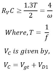
To prevent the gate-cathode junction from breaking down during the negative half-cycle, diode D1 is used. For typical power frequencies, the value of resistor RV and capacitor C to achieve zero output voltage is usually determined through practical experience.

The maximum value of variable resistance RV is given by,
When the resistor Rv has a high value, it takes longer for the capacitor to charge up. So, the firing angle becomes larger, but the average output decreases. Conversely, if we want more output, we need to use a smaller value for Rv.
RC Full-Wave Firing Circuit
The benefits of a full-wave firing circuit compared to a half-wave one are:
- It can supply power to the load during both positive and negative half-cycles thanks to the full-wave bridge diode.
- You can control the firing angle from 0° to 180°.
- The power sent to the load doubles.
- The output voltage is available even during the negative half-cycle.
Below are diagrams showing the RC full-wave firing circuit.
 RC Full Wave Firing Circuit and Related Waveforms
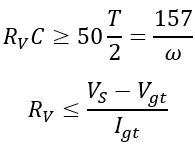
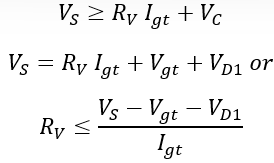
At the start, the capacitor begins to charge from zero volts, with the SCR gate helping keep the voltage low. When the capacitor voltage (VC) hits the SCR's gate trigger voltage (Vgt), the SCR switches on. Then, the alternating current (AC) from the power line, which is converted to direct current (DC) by a full-wave diode bridge, appears across the load. The values for RVC and RV in this circuit are determined by.

Advantages of RC Firing Circuit:
- The RC firing circuit gets rid of the firing angle limits found in the R-firing circuit.
- It lets you adjust the firing angle between 0 and 180 degrees.
- This circuit is affordable, simple, and even works as a snubber circuit.
Disadvantages of RC Firing Circuit:
- The values of RV and C change when the temperature changes.
- The firing angle depends on the RC time constant.
- Fluctuations in the power supply can affect the firing angle.
- It's only suitable for power circuits that use a single thyristor.
- You can only use it in open-loop control systems.
UJT Firing Circuit
The R-firing and RC-firing circuits we talked about earlier create continuous gate pulses, leading to high power loss in the thyristor's gate circuit. To cut down on this power loss, we can use a UJT in the firing circuit. The UJT acts like a relaxation oscillator, generating sharp, repeating pulses with quick rise times. Plus, it remains stable in frequency even if voltage or temperature changes.
 UJT Firing Circuit and Related Waveforms
In the above UJT firing circuit, the UJT starts conducting once the value of the voltage across the capacitor is equal to or more than the peak voltage VP value of the UJT. Now the capacitor starts discharging, and once its voltage decreases to the valley voltage VV of UJT, the UJT will be turned OFF. The capacitor again gets charged to supply voltage and the above process repeats.
Thus whenever UJT conducts it produces pulses at the gate terminal of the thyristor as shown in the waveform. The capacitor charging time depends upon the value of variable resistance RV. Therefore, by varying the value of RV the firing angle can be varied.
|
5 videos|50 docs|46 tests
|
FAQs on Thyristor - Power Electronics - Electrical Engineering (EE)
| 1. What is a thyristor? |  |
| 2. What are the VI characteristics of an SCR? |  |
| 3. What is the two-transistor analogy of a thyristor? |  |
| 4. What are the turn-on methods for a thyristor? |  |
| 5. How can a thyristor be protected from overvoltage or overcurrent? |  |

|
Explore Courses for Electrical Engineering (EE) exam
|

|


